Touch of Moss
I’m teaming up with Alua for the final project.
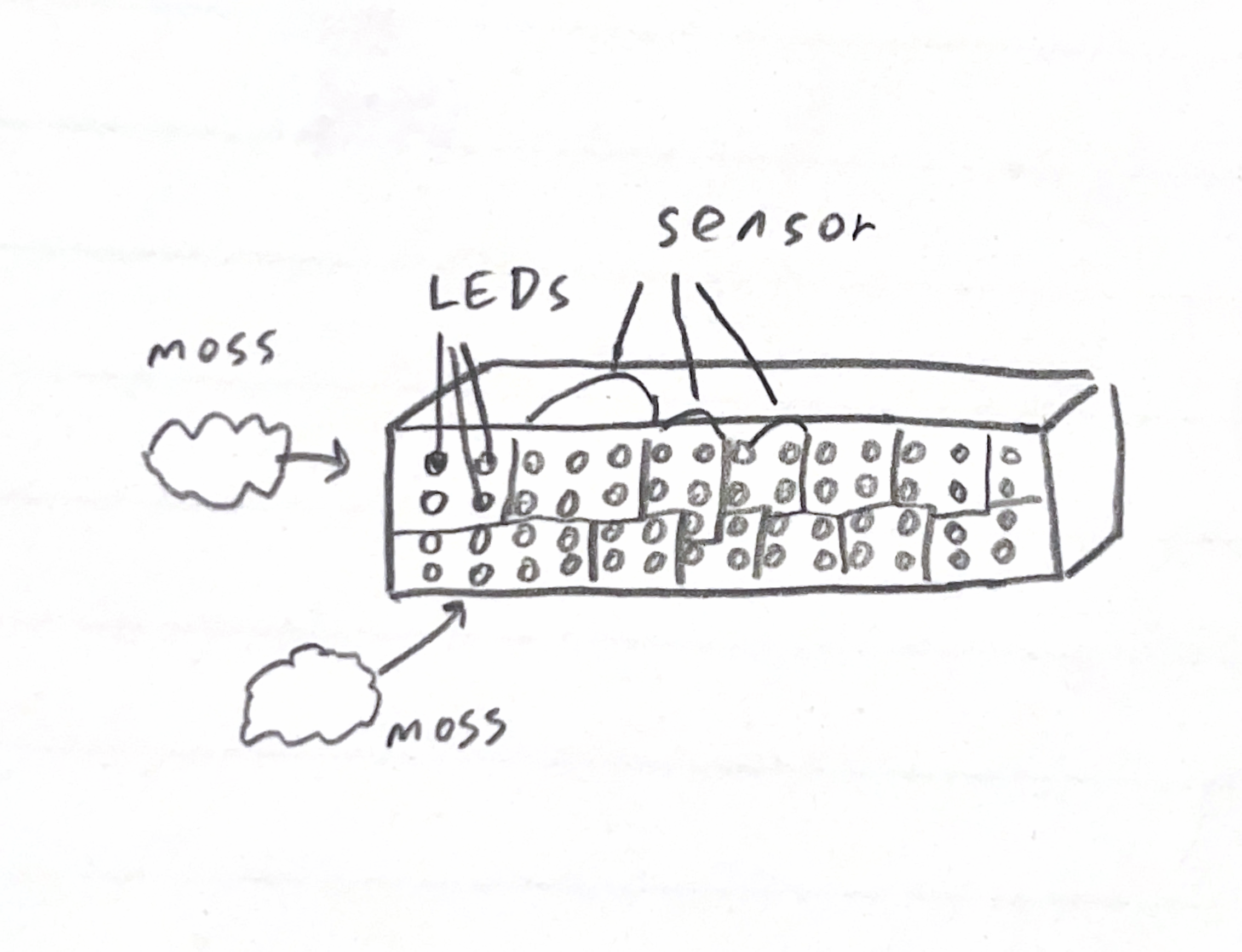
We want to make a wall covered with fake moss and LEDs. When the person touches a certain part of the moss, the surrounding LEDs light up and flare in a heartbeat pattern.
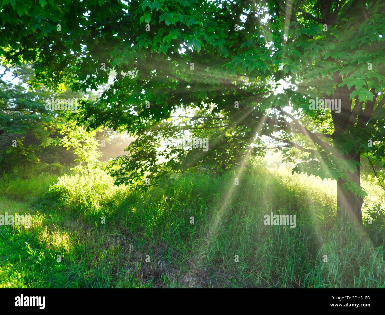
When you touch the moss, the wall breathes back. The heartbeat you see is not just light — it’s the Earth responding to human connection.
Theme : Reconnecting humans with the living rhythm of nature.
Meaning : The wall represents the planet - When a person touches it, the LEDs pulse like a heartbeat, suggesting that human touch revives or affects the Earth’s vitality.
Theme : Our presence leaves ripples in nature.
Meaning: The heartbeat flares visualize how even the smallest human interaction creates energetic responses in the environment. The project becomes a metaphor for how we affect ecosystems — gently or harmfully.
This is the link with the touch sensor DIY
https://blog.arduino.cc/2019/11/13/rapidly-create-your-own-capacitive-multi-touch-sensors-with-this-kit/
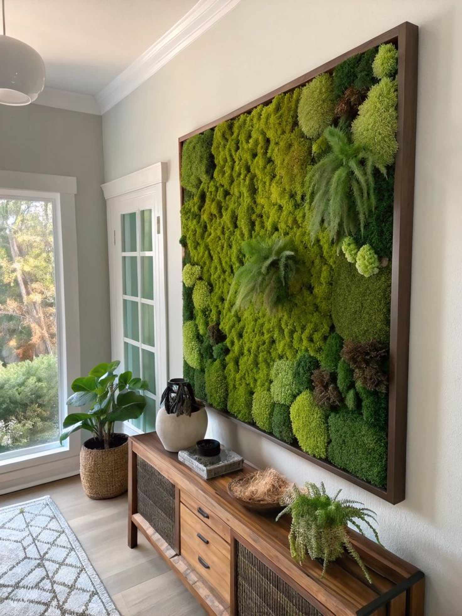
below is our inspiration.
11/11 NOTES
questions and comment from class
- perhaps use screen made with p5 that looks like LED panel
- people wouldnt think to touch the wall. (looks like an art work) perhaps put it on the ground.
- how would you guide the user to touch the wall.
- how about make people step on it.
- piezomicrophone ? for sensing the sound of plant real moss? + plant + instrument
- there is a wall in the lobby in this building
- how would you place the sensor and light with the moss?
talk to prisha ines 예슬 교수님
media pipe https://ai.google.dev/edge/mediapipe/solutions/vision/hand_landmarker ml5js velostat : a pressure-sensitive, conductive plastic material that decreases in electrical resistance when squeezed or compressed
projector kinnect humidifier
11/13/2025
Office Hour with Tom
-
Try user testing first to see how people would interact with the piece.
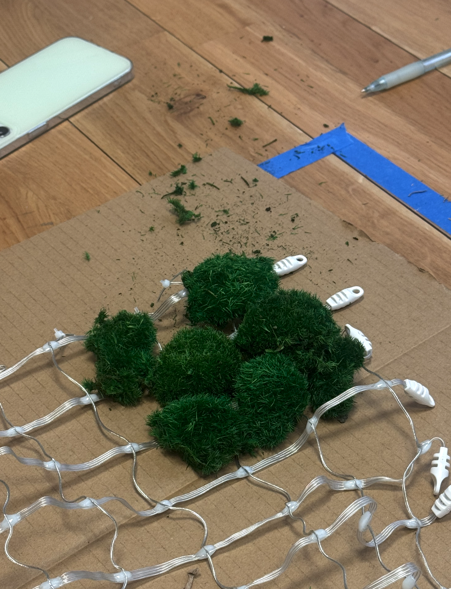
- get moss
- put the moss on the phone and let people interact with it.
OUTPUT
- use projector or screen to see if you get the visual you are imagining.
- if not LED is a way to go but it will be expensive.
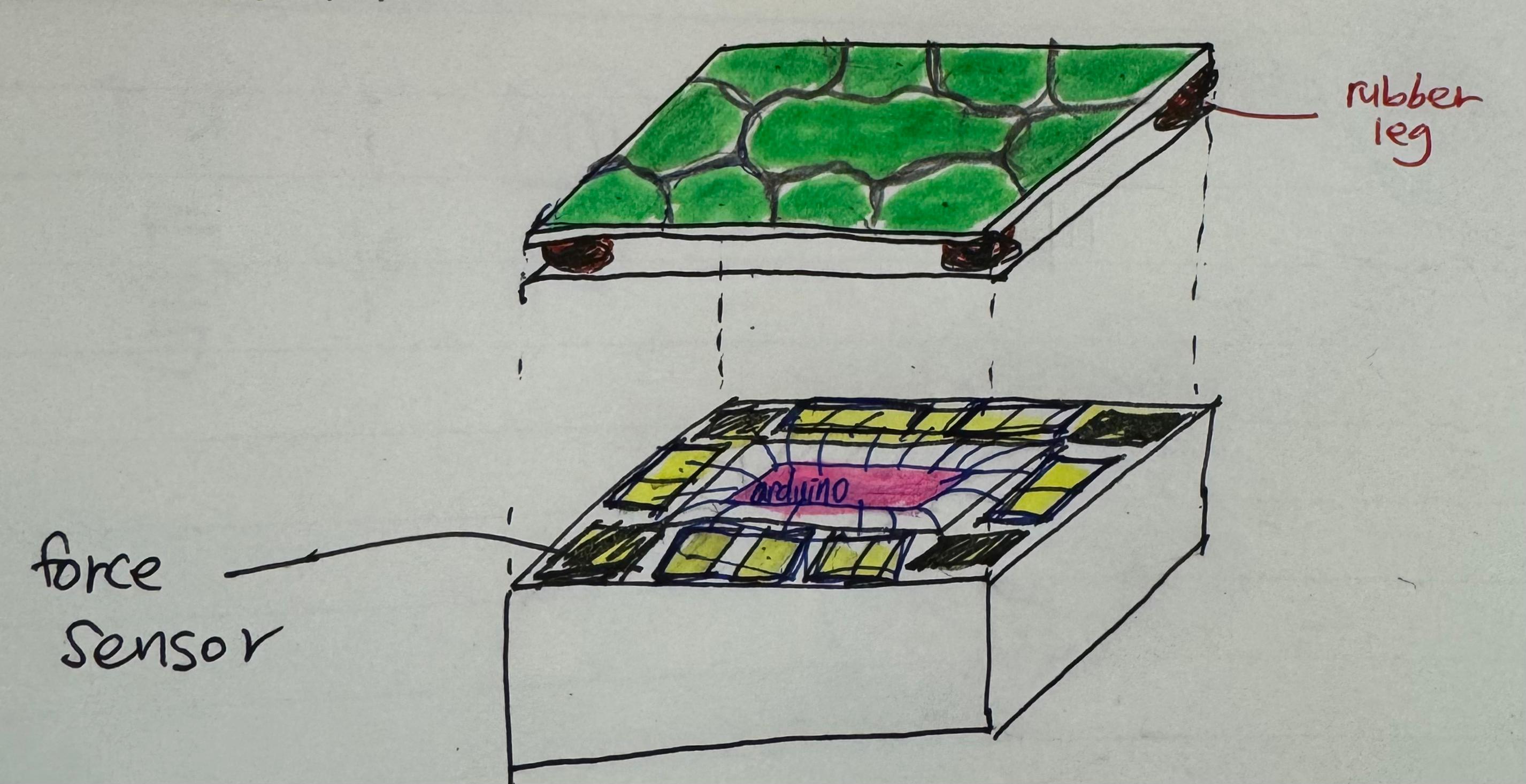
INPUT -force sensor with rubber nob/ wood -vibrance sensor -piezomicrophone(arjun) -velostat(michael)
PHYSICAL DESIGN - maybe have the design in a way that you don’t have to map the whole panel into a grid of sensor
11/14 office hour with Pedro
- NeoPixel LED Outdoor Netting - 20 x 20 LEDs - 1x1 Meter Sizing https://www.adafruit.com/product/6159
- Pedro mentioned there is a LED Net that you can use that will make our project coding easier if we want to go with the LED route.
11/14 office hour with David
-soft button
https://kayitp.wordpress.com/2024/02/16/creating-textile-buttons/
- velostat
https://www.instructables.com/O-mat/
More sensors! https://www.kobakant.at/DIY/ https://www.instructables.com/member/Plusea/
with more office hours with pcomp professors we concluded that we want to make the sensors Digital input like switch than Analog input since we don’t want the users to interact with force.
So we decided to make a soft button with conductive materials like conductive fabric or copper tape.
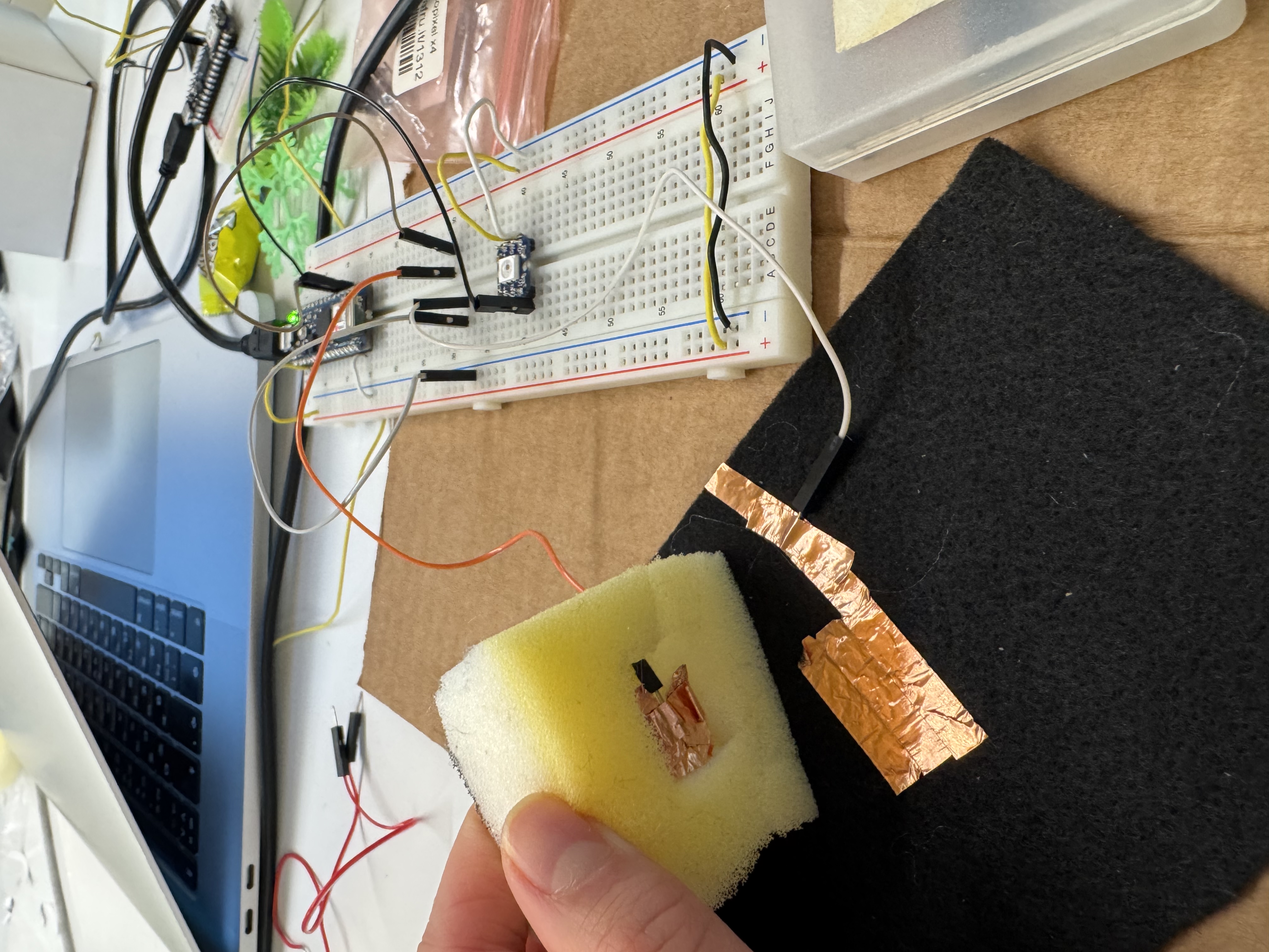
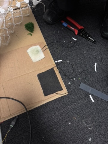
11/17 PROTOTYPE session 1
for our first prototype, we wanted to get one NeoPixel LED turn on with one soft button.
This is how our prototype softbutton looks like.
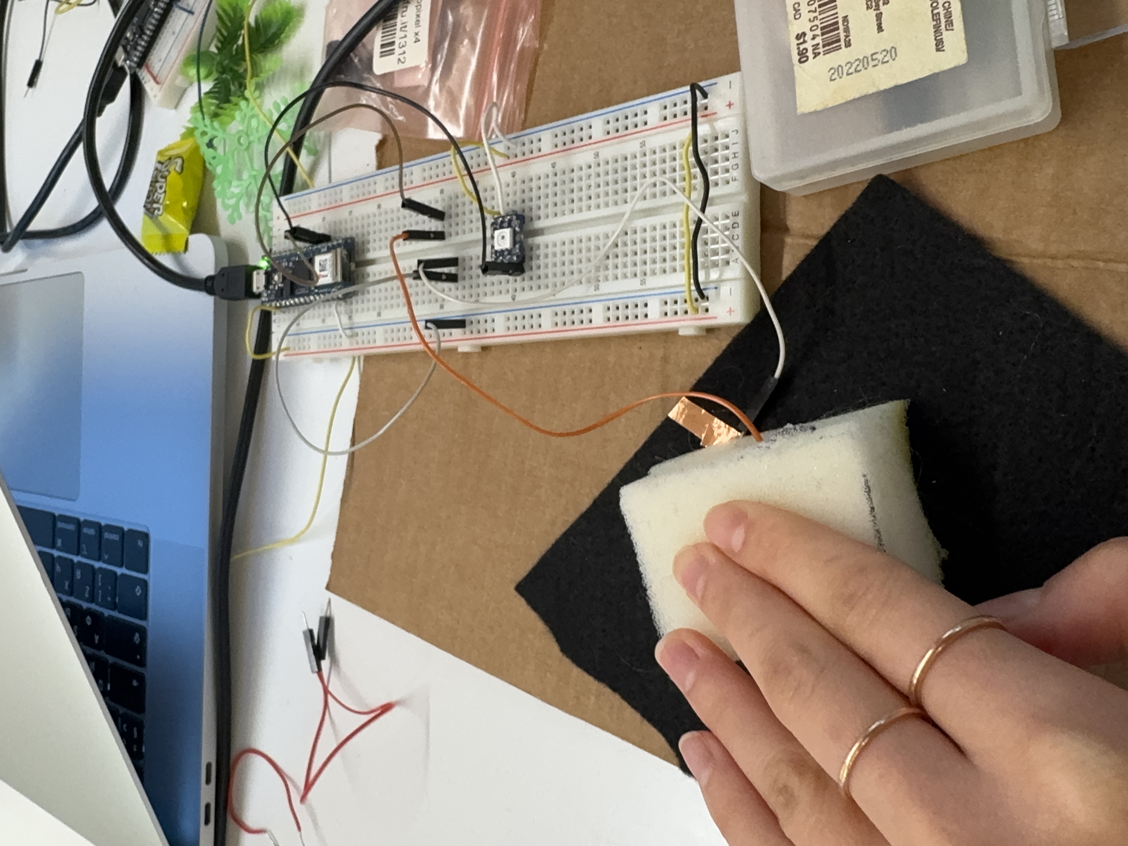
 Before pressing the button. Light turned OFF.
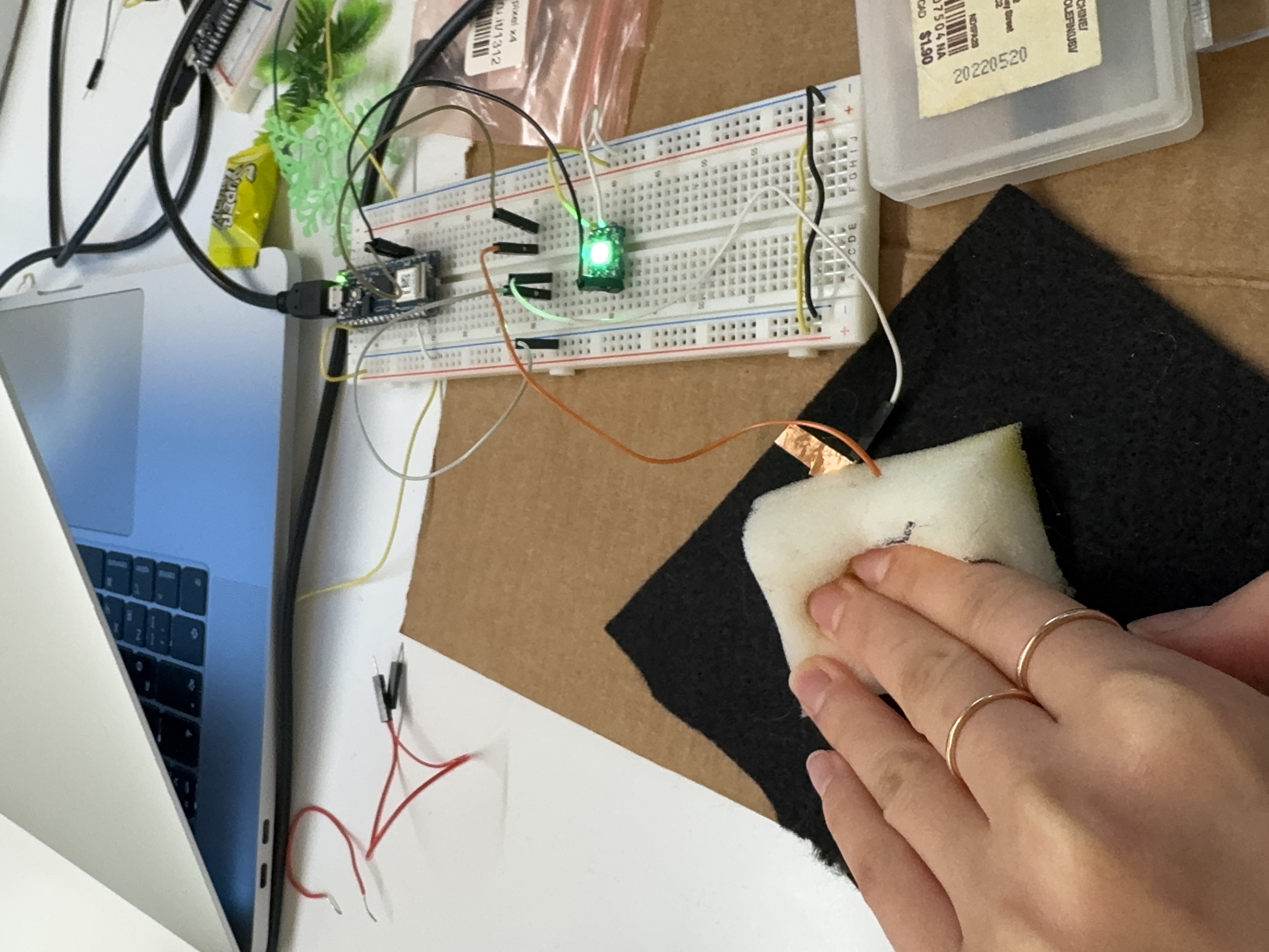
Soft button pressed. Light turned ON.
Below is the Code using the Neopixel library SIMPLE:
// NeoPixel Ring simple sketch (c) 2013 Shae Erisson
// Released under the GPLv3 license to match the rest of the
// Adafruit NeoPixel library

#include <Adafruit_NeoPixel.h>
#ifdef __AVR__
 #include <avr/power.h> // Required for 16 MHz Adafruit Trinket
#endif

// Which pin on the Arduino is connected to the NeoPixels?
#define PIN        2 // NeoPixel data pin

// Button pin
#define BUTTON_PIN 3

// How many NeoPixels are attached to the Arduino?
#define NUMPIXELS 1

Adafruit_NeoPixel pixels(NUMPIXELS, PIN, NEO_GRB + NEO_KHZ800);

void setup() {
#if defined(__AVR_ATtiny85__) && (F_CPU == 16000000)
  clock_prescale_set(clock_div_1);
#endif

  pixels.begin(); // INITIALIZE NeoPixel strip object (REQUIRED)

  // Use internal pull-up resistor for the button
  pinMode(BUTTON_PIN, INPUT_PULLUP);
}

void loop() {
  int buttonState = digitalRead(BUTTON_PIN);

  if (buttonState == LOW) {
    // Button PRESSED -> turn pixel ON (green)
    pixels.setPixelColor(0, pixels.Color(0, 150, 0));
  } else {
    // Button NOT pressed -> turn pixel OFF
    pixels.clear();
  }

  pixels.show();    // Update the LED
  delay(10);        // Small delay for stability
}
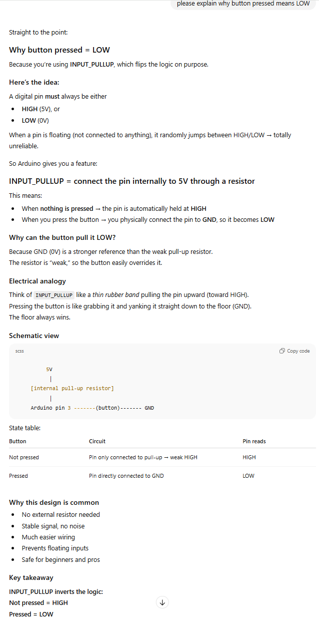
This code is using the reversed logic with activating buttons and here’s why:
11/20 PROTOTYPE session 2
Adafruit NeoPixel LED Net and the Moss are delievered!
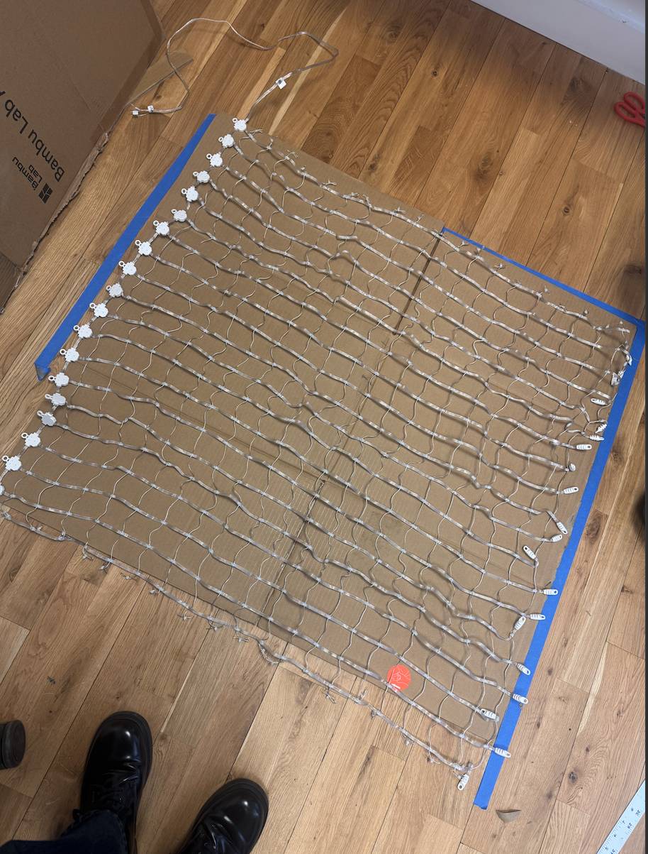
Today we explored how to wire the Neopixel Net to the Arduino and have it light up.
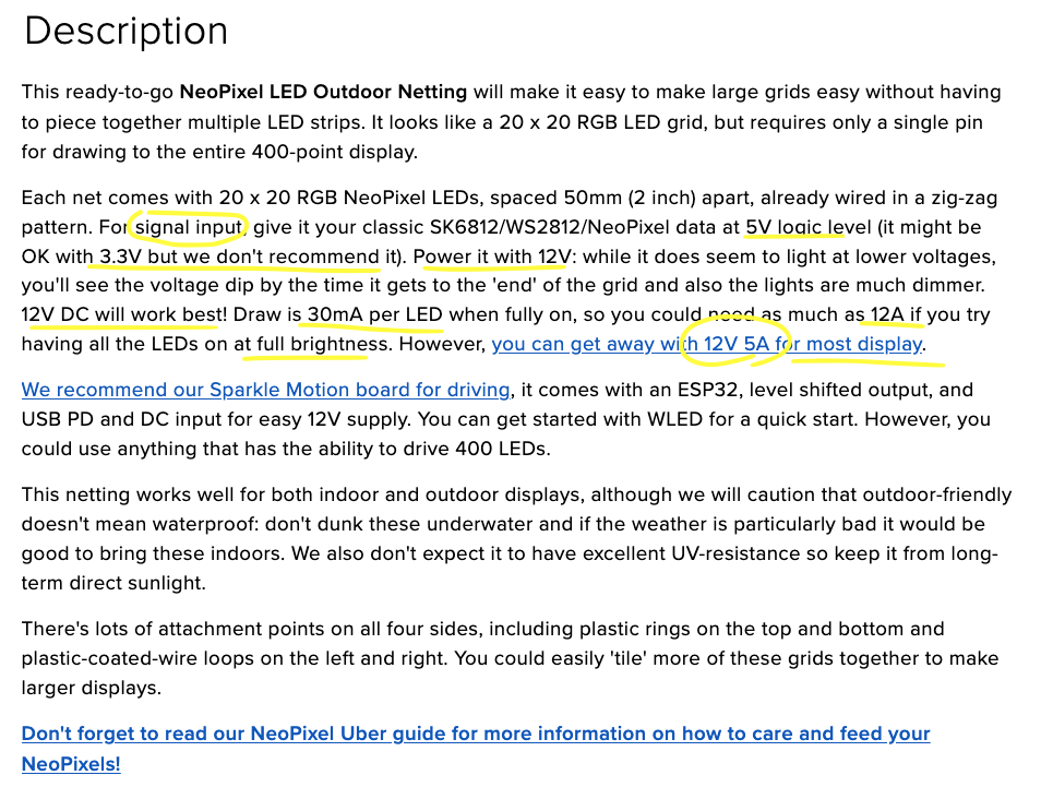 The power code we had was 12V 2A which is way less than what the description says for the full display (12A). We might be fine with getting a few of the LEDs light up but we will definitely be needing a power source that can carry close to 12A. David Rios recommended taking a look at terminal block which will keep the 12V off the breadboard(carries only 1A) and will allow thick wires to carry more Amps.
document for LED net
After so many versions of wiring we finally got the right way to wire the circuit that don’t fry the breadboard, arduino, but still getting enough voltage to light up some LEDs.
The circuit had to have
- Common Ground(Arduino GND = LED net GND)
- ** 330 Ω resistor**
- Placed in series between Arduino pin 2 → LED
DI
- Placed in series between Arduino pin 2 → LED
- 1000 µF capacitor
- Across 12 V + and – right at the LED net input
→ stabilizes inrush current - Put the capacitors:
- Between 12 V + and GND
- As close as possible to the LED net’s power input This helps absorb inrush current when the LED drivers wake up.
- In the shop we had 470 µF so we connected two 470 µF capacitor parallel
- Across 12 V + and – right at the LED net input
- connect 5V to Arduino through usb from Laptop
- connect 12V2A power directly to LED net.
- must never connect the LED net’s 12 V to Arduino 5 V pin.
Only connect ground.
#include <Adafruit_NeoPixel.h>

// ----- LED net config -----
#define PIN_LED    2          // Data pin to LED net
#define WIDTH      20
#define HEIGHT     20
#define NUMPIXELS  (WIDTH * HEIGHT)

// ----- Switch pin -----
#define SW_PIN     3          // only one switch now

Adafruit_NeoPixel strip(NUMPIXELS, PIN_LED, NEO_GRB + NEO_KHZ800);

// ======== HELPERS ========

// Map (x,y) to index
int xyToIndex(int x, int y) {
  if (x < 0 || x >= WIDTH || y < 0 || y >= HEIGHT) return 0;
  return y * WIDTH + x;
}

void clearStrip() {
  for (int i = 0; i < NUMPIXELS; i++) {
    strip.setPixelColor(i, 0, 0, 0);
  }
}

// Fill a rectangular region
void fillRegion(int x0, int y0, int x1, int y1, uint32_t color) {
  if (x0 < 0) x0 = 0;
  if (y0 < 0) y0 = 0;
  if (x1 >= WIDTH)  x1 = WIDTH - 1;
  if (y1 >= HEIGHT) y1 = HEIGHT - 1;

  for (int y = y0; y <= y1; y++) {
    for (int x = x0; x <= x1; x++) {
      int idx = xyToIndex(x, y);
      strip.setPixelColor(idx, color);
    }
  }
}

// ======== SETUP ========

void setup() {
  strip.begin();
  strip.show();

  pinMode(SW_PIN, INPUT_PULLUP); // pressed = LOW
  Serial.begin(115200);
}

// ======== MAIN LOOP ========

void loop() {
  bool sw = (digitalRead(SW_PIN) == LOW);

  clearStrip();

  // ----- Example zone triggered by the ONE switch -----
  if (sw) {
    uint32_t c = strip.Color(0, 150, 0);  // green
    fillRegion(0, 0, 19, 19, c);          // entire net (change to any zone)
  }

  // Also react to p5 mapping messages
  handleSerialFromP5();

  strip.show();
  delay(20);
}

// ======== SERIAL HANDLER ========
// p5 sends: "x,y\n" to light a pixel

void handleSerialFromP5() {
  static char line[16];
  static byte idx = 0;

  while (Serial.available() > 0) {
    char c = Serial.read();

    if (c == '\n' || c == '\r') {
      if (idx > 0) {
        line[idx] = '\0';
        int x, y;
        if (sscanf(line, "%d,%d", &x, &y) == 2) {
          int index = xyToIndex(x, y);
          strip.setPixelColor(index, strip.Color(150, 150, 150));
        }
      }
      idx = 0;
    } else {
      if (idx < sizeof(line) - 1) {
        line[idx++] = c;
      } else {
        idx = 0;
      }
    }
  }
}
Switch Wiring
Since you’re using ONE switch:
- One leg → Pin 3
- Other leg → GND
Because the sketch uses
INPUT_PULLUP: - Not pressed → HIGH
- Pressed → LOW (your trigger)
Our very first time running the code with the LED with a default switch wired. FAILED.
One wire was not connected properly! Now it works! yay!
11/22
we are going to make a part of the whole panel with all the elements in.
starting with making the switch with moss on top.
#include <Adafruit_NeoPixel.h>

// ----- LED net config -----
#define PIN_LED    2
#define WIDTH      20
#define HEIGHT     20
#define NUMPIXELS  (WIDTH * HEIGHT)

// ----- Switch pins -----
#define SW1_PIN     3      // switch 1
#define SW2_PIN     4      // switch 2

Adafruit_NeoPixel strip(NUMPIXELS, PIN_LED, NEO_GRB + NEO_KHZ800);

// ======== HELPERS ========

int xyToIndex(int x, int y) {
  if (x < 0 || x >= WIDTH || y < 0 || y >= HEIGHT) return 0;
  return y * WIDTH + x;
}

void clearStrip() {
  for (int i = 0; i < NUMPIXELS; i++) {
    strip.setPixelColor(i, 0, 0, 0);
  }
}

// fill a rectangle
void fillRegion(int x0, int y0, int x1, int y1, uint32_t color) {
  if (x0 < 0) x0 = 0;
  if (y0 < 0) y0 = 0;
  if (x1 >= WIDTH)  x1 = WIDTH - 1;
  if (y1 >= HEIGHT) y1 = HEIGHT - 1;

  for (int y = y0; y <= y1; y++) {
    for (int x = x0; x <= x1; x++) {
      int idx = xyToIndex(x, y);
      strip.setPixelColor(idx, color);
    }
  }
}

// ======== SETUP ========

void setup() {
  strip.begin();
  strip.show();

  pinMode(SW1_PIN, INPUT_PULLUP);   // pressed = LOW
  pinMode(SW2_PIN, INPUT_PULLUP);   // pressed = LOW

  Serial.begin(115200);
}

// ======== MAIN LOOP ========

void loop() {
  bool sw1 = (digitalRead(SW1_PIN) == LOW);
  bool sw2 = (digitalRead(SW2_PIN) == LOW);

  clearStrip();

  // ----- Switch 1 → Entire net green -----
  if (sw1) {
    uint32_t c1 = strip.Color(0, 150, 0);
    fillRegion(0, 0, 19, 19, c1);
  }

  // ----- Switch 2 → Example: Top half blue -----
  if (sw2) {
    uint32_t c2 = strip.Color(0, 0, 150);
    fillRegion(0, 0, 19, 9, c2);   // first 10 rows
  }

  // Combine with p5 input mapping
  handleSerialFromP5();

  strip.show();
  delay(20);
}

// ======== SERIAL HANDLER ========
// p5 sends "x,y\n"
void handleSerialFromP5() {
  static char line[16];
  static byte idx = 0;

  while (Serial.available() > 0) {
    char c = Serial.read();

    if (c == '\n' || c == '\r') {
      if (idx > 0) {
        line[idx] = '\0';
        int x, y;
        if (sscanf(line, "%d,%d", &x, &y) == 2) {
          int index = xyToIndex(x, y);
          strip.setPixelColor(index, strip.Color(150, 150, 150));
        }
      }
      idx = 0;
    } else {
      if (idx < sizeof(line) - 1) {
        line[idx++] = c;
      } else {
        idx = 0;
      }
    }
  }
}
11/24
Today we did office hour with Yeseul Song, and got some more feedback on our project. After the office hour with her we feel the need to do some more research on moss to make our piece more persuasive with strong concept.
Summer and Alua-

Sharing some more thoughts after the meeting.

1. Quick search for moss that might be nice to start with: [https://www.youtube.com/watch?v=VVeBSKK88Ig](https://www.youtube.com/watch?v=VVeBSKK88Ig)
I think moss is truly amazing, and maybe your project can be built thoughtfully in a way to shine on it.

2. Visual effects like rippling that you mentioned will be more clearly perceived with less number of interaction points since it takes time to show the effects and can be confusing if it collides with interaction.

3. If you end up making each moss a pixel (I think it was one of your ideas..), you could use each moss ball illuminating from the back light by having a bit of gap between the moss layer and the LEDs.

4. If you're intending to make more elaborate visual effects, projecting might be more effective than LEDs if that works with the aesthetics you're going for. Rear project is also something you can consider. An example from Callie Page: [https://calliepage.com/projects/reel-it-in](https://calliepage.com/projects/reel-it-in)

Good luck.
Yeseul
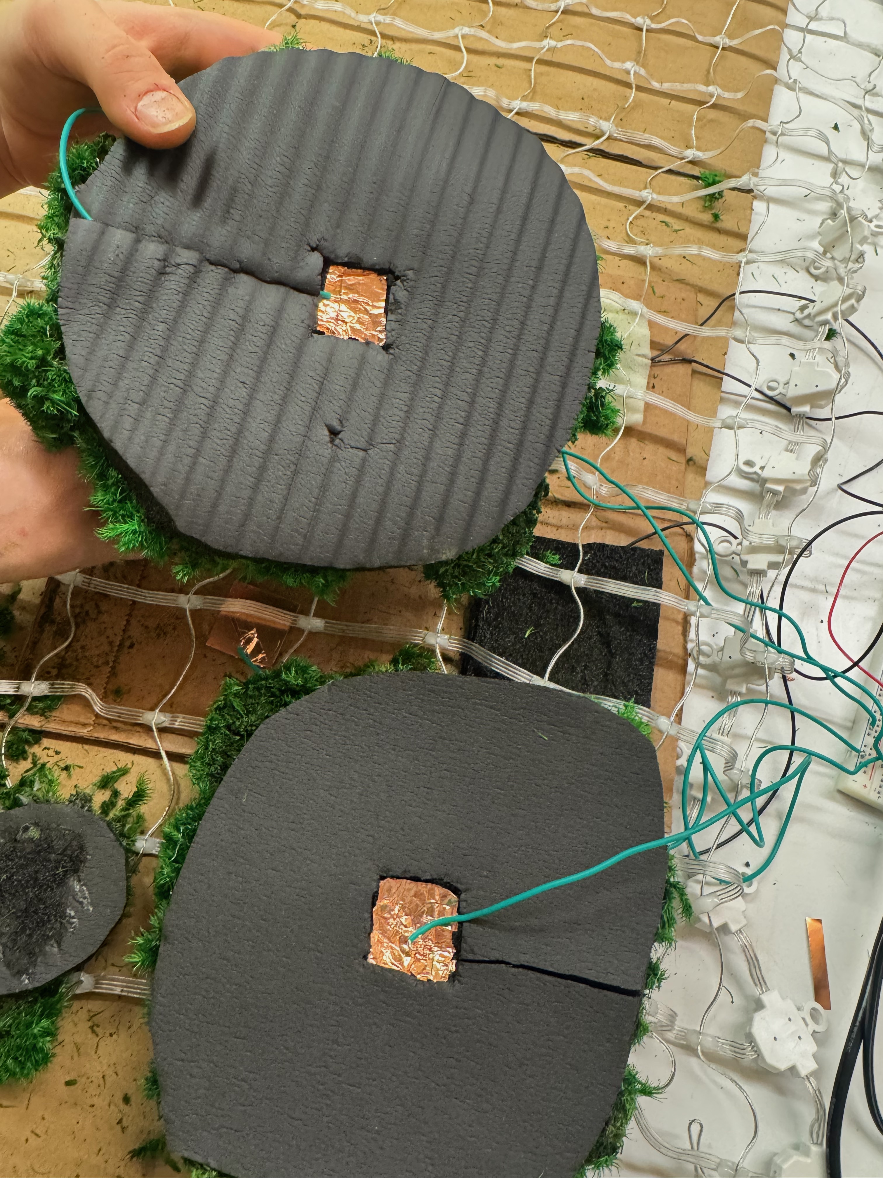
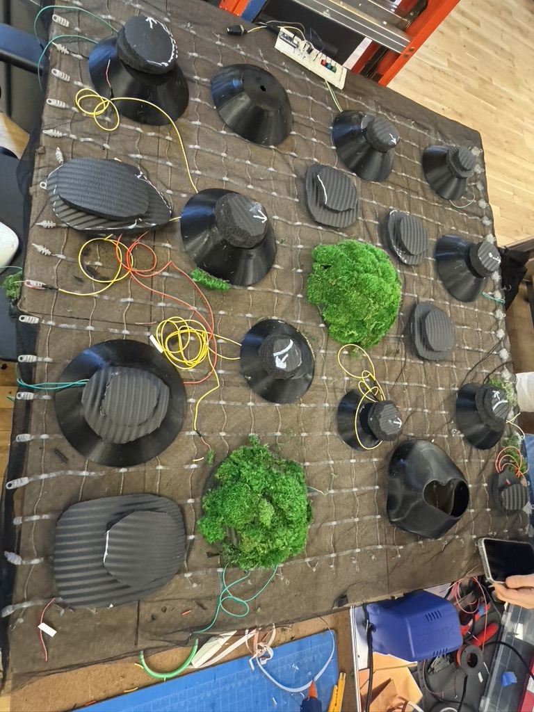
But for today since we need to prepare for a play test for tomorrow, we added two more switches with different fabrication of moss blobs so that we could get some feed back on both switches. We tried different method of making the blob to see how it looks and feels. how much pressure would be ideal to touch/press the moss to turn on the lights underneath. also we found some black sheer cloth in the soft lab which we like the effect it’s giving !
This is how the switches look under the moss blob.
This is the code that is connected to 4 switches (PIN D3,4,5,6) and NeoPixel Net.
#include <Adafruit_NeoPixel.h>

// ----- LED net config -----
#define PIN_LED    2
#define WIDTH      20
#define HEIGHT     20
#define NUMPIXELS  (WIDTH * HEIGHT)

// ----- Switch pins -----
#define SW1_PIN    3   // switch 1
#define SW2_PIN    4   // switch 2
#define SW3_PIN    5   // switch 3
#define SW4_PIN    6   // switch 4

Adafruit_NeoPixel strip(NUMPIXELS, PIN_LED, NEO_GRB + NEO_KHZ800);

// ======== HELPERS ========

// Map (x,y) to index (row by row)
int xyToIndex(int x, int y) {
  if (x < 0 || x >= WIDTH || y < 0 || y >= HEIGHT) return 0;
  return y * WIDTH + x;
}

void clearStrip() {
  for (int i = 0; i < NUMPIXELS; i++) {
    strip.setPixelColor(i, 0, 0, 0);
  }
}

// Fill a rectangular region (inclusive x0..x1, y0..y1)
void fillRegion(int x0, int y0, int x1, int y1, uint32_t color) {
  if (x0 < 0) x0 = 0;
  if (y0 < 0) y0 = 0;
  if (x1 >= WIDTH)  x1 = WIDTH - 1;
  if (y1 >= HEIGHT) y1 = HEIGHT - 1;

  for (int y = y0; y <= y1; y++) {
    for (int x = x0; x <= x1; x++) {
      int idx = xyToIndex(x, y);
      strip.setPixelColor(idx, color);
    }
  }
}

// ======== SETUP ========

void setup() {
  strip.begin();
  strip.show();

  pinMode(SW1_PIN, INPUT_PULLUP);  // pressed = LOW
  pinMode(SW2_PIN, INPUT_PULLUP);  // pressed = LOW
  pinMode(SW3_PIN, INPUT_PULLUP);  // pressed = LOW
  pinMode(SW4_PIN, INPUT_PULLUP);  // pressed = LOW

  Serial.begin(115200);
}

// ======== MAIN LOOP ========

void loop() {
  bool sw1 = (digitalRead(SW1_PIN) == LOW);
  bool sw2 = (digitalRead(SW2_PIN) == LOW);
  bool sw3 = (digitalRead(SW3_PIN) == LOW);
  bool sw4 = (digitalRead(SW4_PIN) == LOW);

  clearStrip();

  // ----- Map 4 switches to 4 areas (quadrants) -----
  // Top-left  (x 0–9,  y 0–9)
  if (sw1) {
    uint32_t c1 = strip.Color(150, 0, 0);   // red-ish
    fillRegion(0, 0, 9, 9, c1);
  }

  // Top-right (x 10–19, y 0–9)
  if (sw2) {
    uint32_t c2 = strip.Color(0, 150, 0);   // green-ish
    fillRegion(10, 0, 19, 9, c2);
  }

  // Bottom-left (x 0–9, y 10–19)
  if (sw3) {
    uint32_t c3 = strip.Color(0, 0, 150);   // blue-ish
    fillRegion(0, 10, 9, 19, c3);
  }

  // Bottom-right (x 10–19, y 10–19)
  if (sw4) {
    uint32_t c4 = strip.Color(150, 150, 0); // yellow-ish
    fillRegion(10, 10, 19, 19, c4);
  }

  // p5 can still light individual pixels on top
  handleSerialFromP5();

  strip.show();
  delay(20);
}

// ======== SERIAL HANDLER ========
// p5 sends: "x,y\n" to light a pixel

void handleSerialFromP5() {
  static char line[16];
  static byte idx = 0;

  while (Serial.available() > 0) {
    char c = Serial.read();

    if (c == '\n' || c == '\r') {
      if (idx > 0) {
        line[idx] = '\0';
        int x, y;
        if (sscanf(line, "%d,%d", &x, &y) == 2) {
          int index = xyToIndex(x, y);
          strip.setPixelColor(index, strip.Color(150, 150, 150));
        }
      }
      idx = 0;
    } else {
      if (idx < sizeof(line) - 1) {
        line[idx++] = c;
      } else {
        idx = 0;
      }
    }
  }
}
moss traits
- it illuminates
- sense temperature > moderate surrounding temperature
more ideas after feedbacks / research ultrasonic mistmaker vibration motor humidity sensor sound output
11/25
Playtest review
- Tom’s feedback : have unique animations that drags the user to engage with the piece longer.
- Danny’s feedback: come up with some animation/system that has randomness or uniqueness, or unexpectedness so that it makes the piece more like nature, reminds the users to have more respect towards nature.
- Other student’s feedback :
- adding sound of nature would help
- have variations with the visual of the moss blobs
- have different animation with combination of more than one blob touching at once
- subtle change in color would be interesting
- adding mist with the humidity sensor
- or just add mist on the grass so that it feels more like real moss
- My thought after this :
- we should have some cushions around the piece to guide the user to sit down and interact so that it doesn’t lead the users to step on it.
- talk with Alua after playtest:
- While I was doing the playtest, Alua met with David Rios to ask about the sensors/outputs that we are thinking of adding, he said ultrasonic mistmaker is going to be hard to make it work.
- So based on the playtest and people’s feedback, we decided to focus on getting diverse animation for the LED lights that makes the interaction more engaging and interactive, and figure out sound output. since I already worked with playing mp4 files with soundboard, I can easily figure that part out. We just have to have what kind of sound would make more sense and enhance the experience.
- For this Thanksgiving break, I’m going to work on the 3D modeling / 3D printing of the blob structure, and Alua’s going to work on the LED animation code.
11/28
Alua and I came to a conclusion that we will have a base structure for the elevation of the moss blobs with 3d prints and the switches will be sitting on top of the base structure. We will have different sizes of moss blobs.
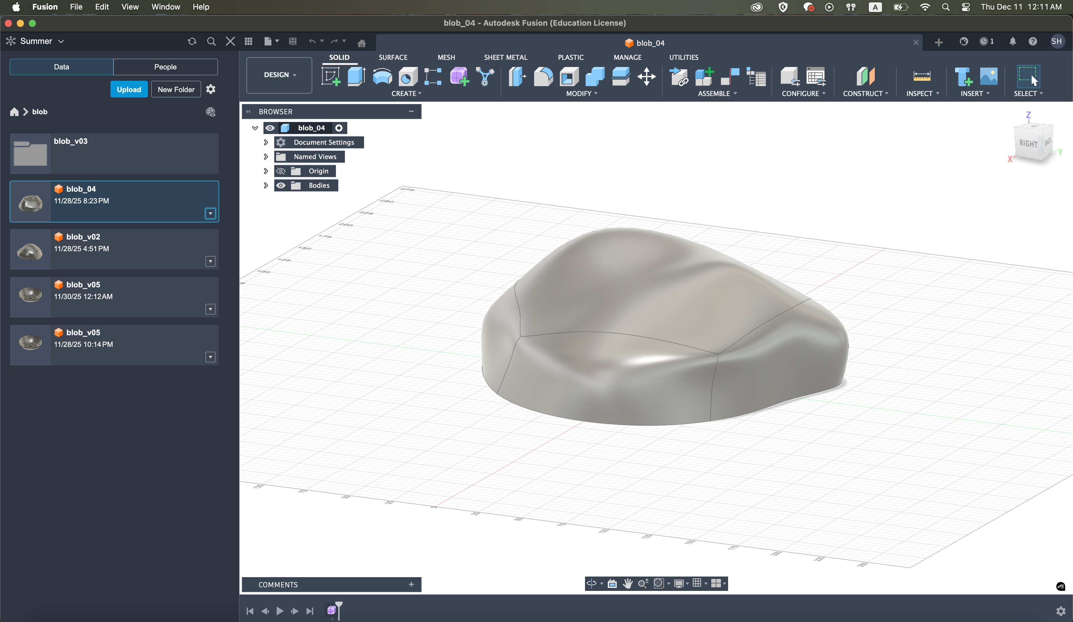
at first I made the shape of the blob structure to be more like randomly distorted more natural rock like shape, but for time efficiency we had to make it identical upsidedown bowl like shape with a hole on the top for the wires to go through. we are planning to have the randomness in shape during the process of moss attaching.
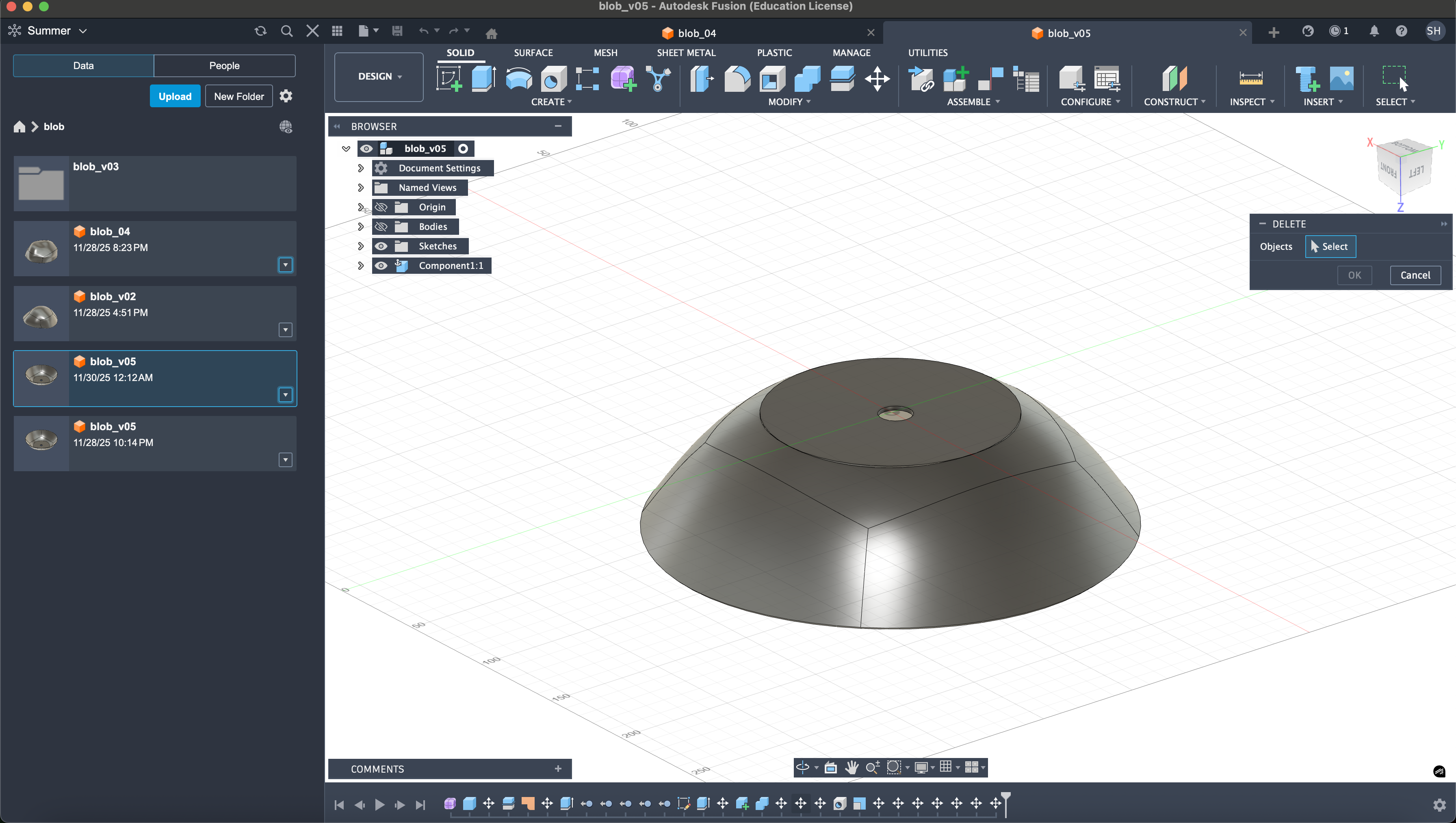
during thanksgiving break, I took advantage of the empty floor and dominated the 3d printers to print 14 blob structure that will be the base of our moss blobs.(jkjk i just used two 3d printers at once Alua’s and my account) It was my first time using Fusion360 and figuring out 3d printer workflow. It was pretty straightforward and I had fun playing with it. I’m glad that I know how to use 3d printer now.
12/6
I worked on the sound board today. Found a minute of recording of the sound of moss online, and planning on looping the wav file. Adafruit FX soundboard storage was too small that I had to compress the stereo WAV file to Mono OGG file.
and for the first 3hours I realized later on that I was dealing with the broken sound board…
as soon as I changed the sound board to a different one it started working again…
Sometimes believing in me and doubting the actual compoent is not working would solve way faster,,,,
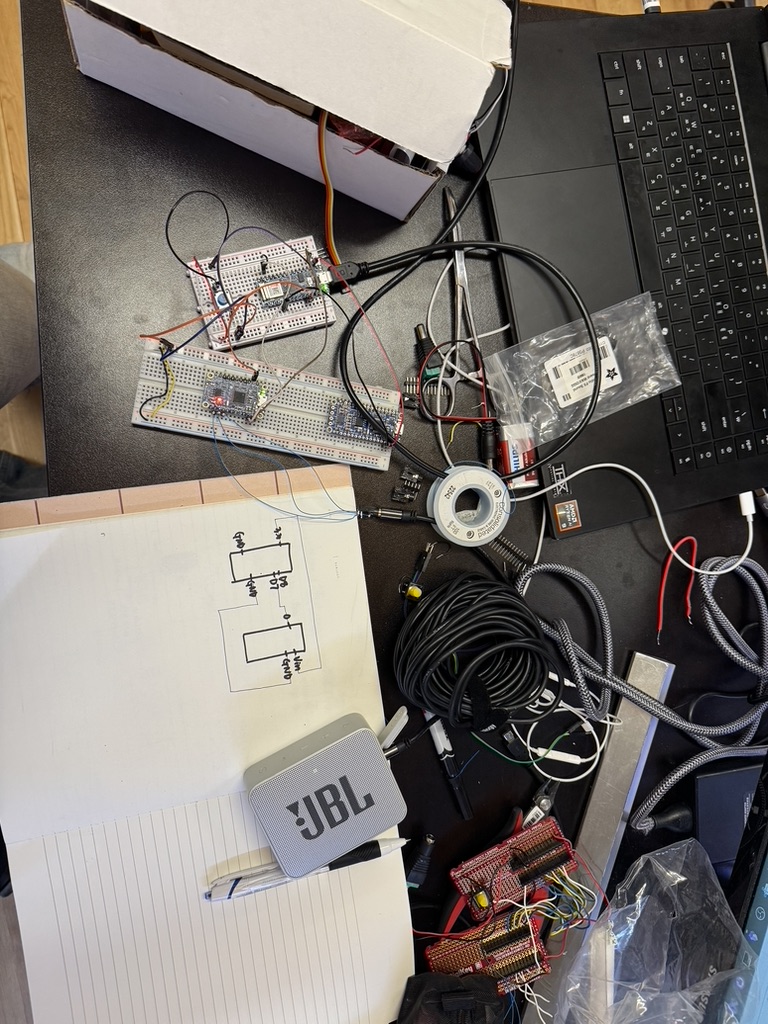
code for connecting arduino/soundboard/LED
#include <Adafruit_NeoPixel.h>

// Pin definitions
#define SOUND_PIN 3        // Connected to soundboard pin 0 (trigger)
#define SOUND_RST 5        // Connected to soundboard RST pin (CONNECT THIS!)
#define BUTTON_PIN 4       // Button input
#define LED_PIN 2          // NeoPixel data pin

// LED setup - adjust these based on your net size
#define NUM_LEDS 64        // Total number of LEDs in your net (change if different)
#define LEDS_PER_ROW 8     // Number of LEDs in first row (change if different)

// Create NeoPixel object
Adafruit_NeoPixel strip = Adafruit_NeoPixel(NUM_LEDS, LED_PIN, NEO_GRB + NEO_KHZ800);

// Variables to track state
int buttonPresses = 0;           // Count how many times button was pressed
bool lastButtonState = HIGH;     // Previous button state (HIGH = not pressed)
bool currentButtonState = HIGH;  // Current button state
unsigned long lastDebounceTime = 0;  // Last time button state changed
unsigned long debounceDelay = 50;    // Debounce time in milliseconds

// LED blinking variables
unsigned long previousMillis = 0;    // Stores last time LED was updated
const long blinkInterval = 500;      // Blink interval (500ms = 0.5 seconds)
bool ledState = false;               // Current LED state (on/off)

// Sound trigger variables
bool soundIsPlaying = false;
unsigned long soundTriggerTime = 0;
bool soundTriggered = false;
unsigned long soundStopTime = 0;       // When sound was stopped
const long soundOffDuration = 5000;    // Keep sound off for 5 seconds (5000ms)

void setup() {
  // Initialize pins
  pinMode(SOUND_PIN, OUTPUT);
  pinMode(SOUND_RST, OUTPUT);
  pinMode(BUTTON_PIN, INPUT_PULLUP);  // Use internal pullup resistor

  // Set initial states - IMPORTANT!
  digitalWrite(SOUND_PIN, HIGH);   // Trigger pin HIGH (not triggered)
  digitalWrite(SOUND_RST, HIGH);   // RST pin HIGH (not resetting)

  // Initialize NeoPixel strip
  strip.begin();
  strip.show(); // Initialize all pixels to 'off'

  // Optional: for debugging
  Serial.begin(9600);
  Serial.println("Arduino Started - Ready!");
}

void loop() {
  // Read the button state
  int reading = digitalRead(BUTTON_PIN);

  // Check if button state changed (debouncing)
  if (reading != lastButtonState) {
    lastDebounceTime = millis();
  }

  // If enough time has passed, accept the new button state
  if ((millis() - lastDebounceTime) > debounceDelay) {
    // If button state has changed
    if (reading != currentButtonState) {
      currentButtonState = reading;

      // If button was just pressed (LOW = pressed with INPUT_PULLUP)
      if (currentButtonState == LOW) {
        buttonPresses++;
        Serial.print("Button presses: ");
        Serial.println(buttonPresses);

        // Reset sound trigger flag when leaving the 1-3 press state
        if (buttonPresses > 3) {
          soundTriggered = false;
        }
      }
    }
  }

  lastButtonState = reading;

  // Control behavior based on number of presses
  if (buttonPresses == 0) {
    // Initial state: everything off
    digitalWrite(SOUND_RST, HIGH);  // Make sure RST is HIGH (not resetting)
    soundIsPlaying = false;
    strip.clear();
    strip.show();

  } else if (buttonPresses > 0 && buttonPresses <= 3) {
    // 1-3 presses: sound on, first row lit (steady)

    // Make sure RST is HIGH (not resetting) so sound can play
    digitalWrite(SOUND_RST, HIGH);

    // Trigger sound only once when entering this state
    if (!soundTriggered) {
      Serial.println("Attempting to trigger sound...");
      Serial.print("SOUND_PIN before trigger: ");
      Serial.println(digitalRead(SOUND_PIN));
      Serial.print("SOUND_RST before trigger: ");
      Serial.println(digitalRead(SOUND_RST));

      triggerSound();
      soundTriggered = true;
      soundIsPlaying = true;

      Serial.print("SOUND_PIN after trigger: ");
      Serial.println(digitalRead(SOUND_PIN));
    }

    // Light up first row only (steady)
    strip.clear();
    for (int i = 0; i < LEDS_PER_ROW; i++) {
      strip.setPixelColor(i, strip.Color(255, 255, 255)); // White color
    }
    strip.show();

  } else {
    // More than 3 presses: sound off, LEDs blinking

    // Stop sound and start timing when entering this state
    if (soundIsPlaying) {
      soundIsPlaying = false;
      soundStopTime = millis();  // Record when we stopped the sound
      Serial.println("Sound stopped - holding RST LOW for 5 seconds");
    }

    // Check if 5 seconds have passed since stopping
    unsigned long currentMillis = millis();

    // Hold RST pin LOW for the full 5 seconds to keep sound off
    if (currentMillis - soundStopTime < soundOffDuration) {
      digitalWrite(SOUND_RST, LOW);  // Keep RST LOW = sound stays off
    } else {
      digitalWrite(SOUND_RST, HIGH); // Release RST after 5 seconds
      // 5 seconds have passed, reset button presses to allow sound again
      buttonPresses = 0;
      soundTriggered = false;  // Reset trigger flag so sound can play again
      Serial.println("5 seconds passed - resetting to ready state");
    }

    // Blink the first row
    if (currentMillis - previousMillis >= blinkInterval) {
      previousMillis = currentMillis;
      ledState = !ledState;  // Toggle LED state

      if (ledState) {
        // Turn on first row
        for (int i = 0; i < LEDS_PER_ROW; i++) {
          strip.setPixelColor(i, strip.Color(255, 255, 255));
        }
      } else {
        // Turn off all LEDs
        strip.clear();
      }
      strip.show();
    }
  }
}

// Function to trigger sound (create a falling edge pulse)
void triggerSound() {
  digitalWrite(SOUND_PIN, LOW);   // Pull LOW to trigger
  delay(100);                     // Longer pulse (100ms instead of 10ms)
  digitalWrite(SOUND_PIN, HIGH);  // Back to HIGH
  Serial.println("Sound triggered!");
}

// Function to stop sound using RST pin
void stopSound() {
  digitalWrite(SOUND_RST, LOW);   // Pull RST LOW to reset/stop
  delay(10);                      // Short pulse
  digitalWrite(SOUND_RST, HIGH);  // Back to HIGH
  Serial.println("Sound stopped!");
}
12/7 making soft switches
I spent the whole day from 11am to 5am(+1) making switches for the moss blobs.
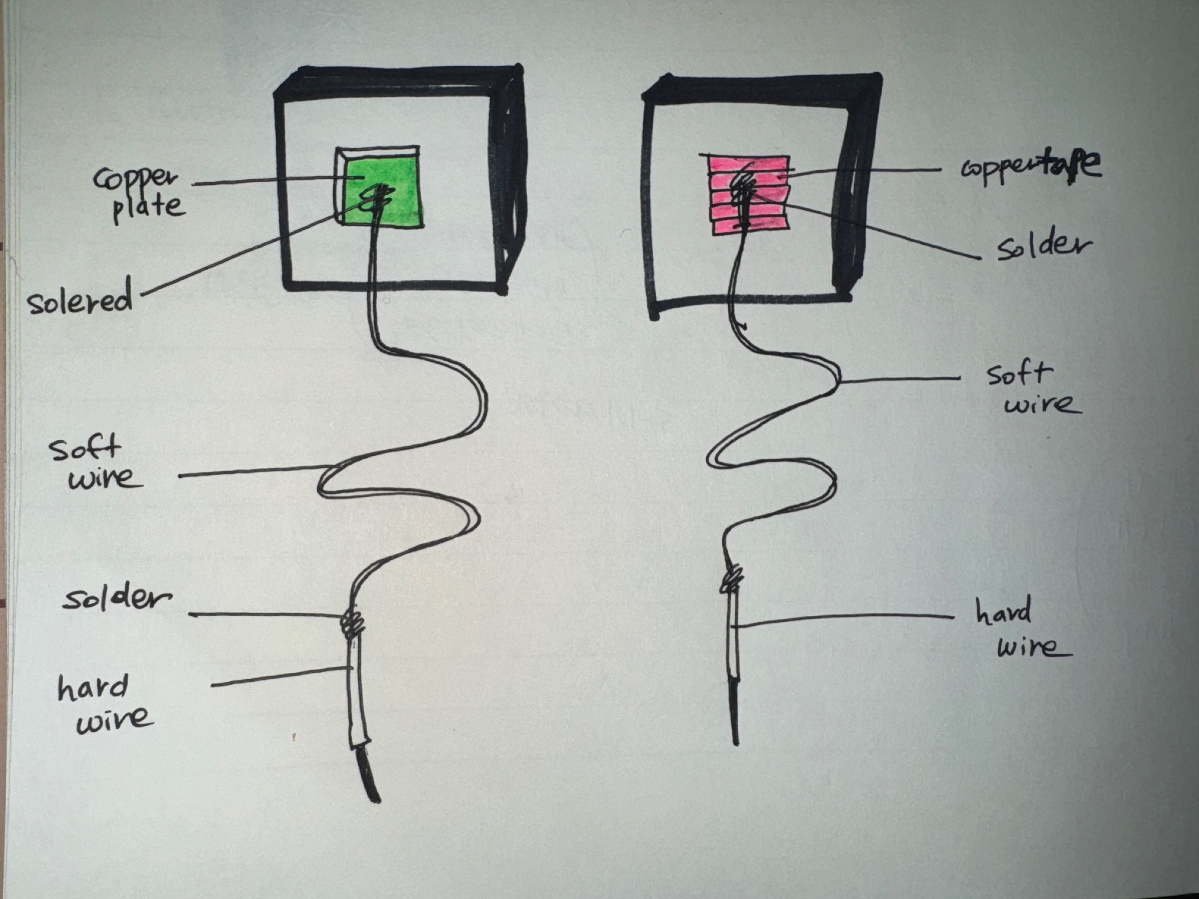
The materials we used : Yoga Mat, copper plate, copper tape, shrinking tubes, soft wires, hard wires, soldering, blowing machine.
below is the drawing of how our soft switch is made. we attached copper plate on one yoga mat and copper tape on the other yoga mat and connected them with soft wires. But soft wires were hard to plug into breadboard so we soldered hard wire at the end of the soft wires so that we can securely and easily connect it to breadboard.
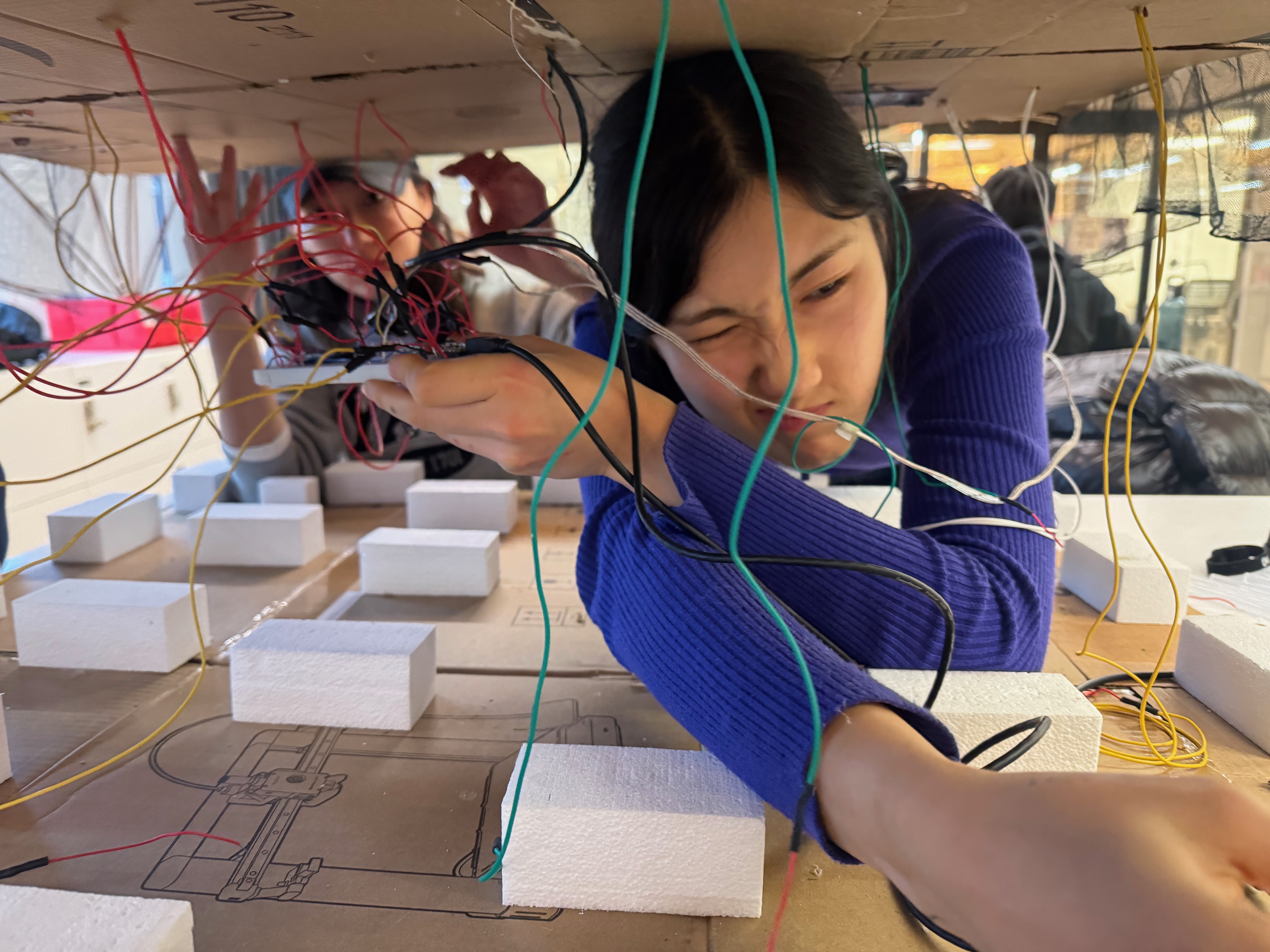
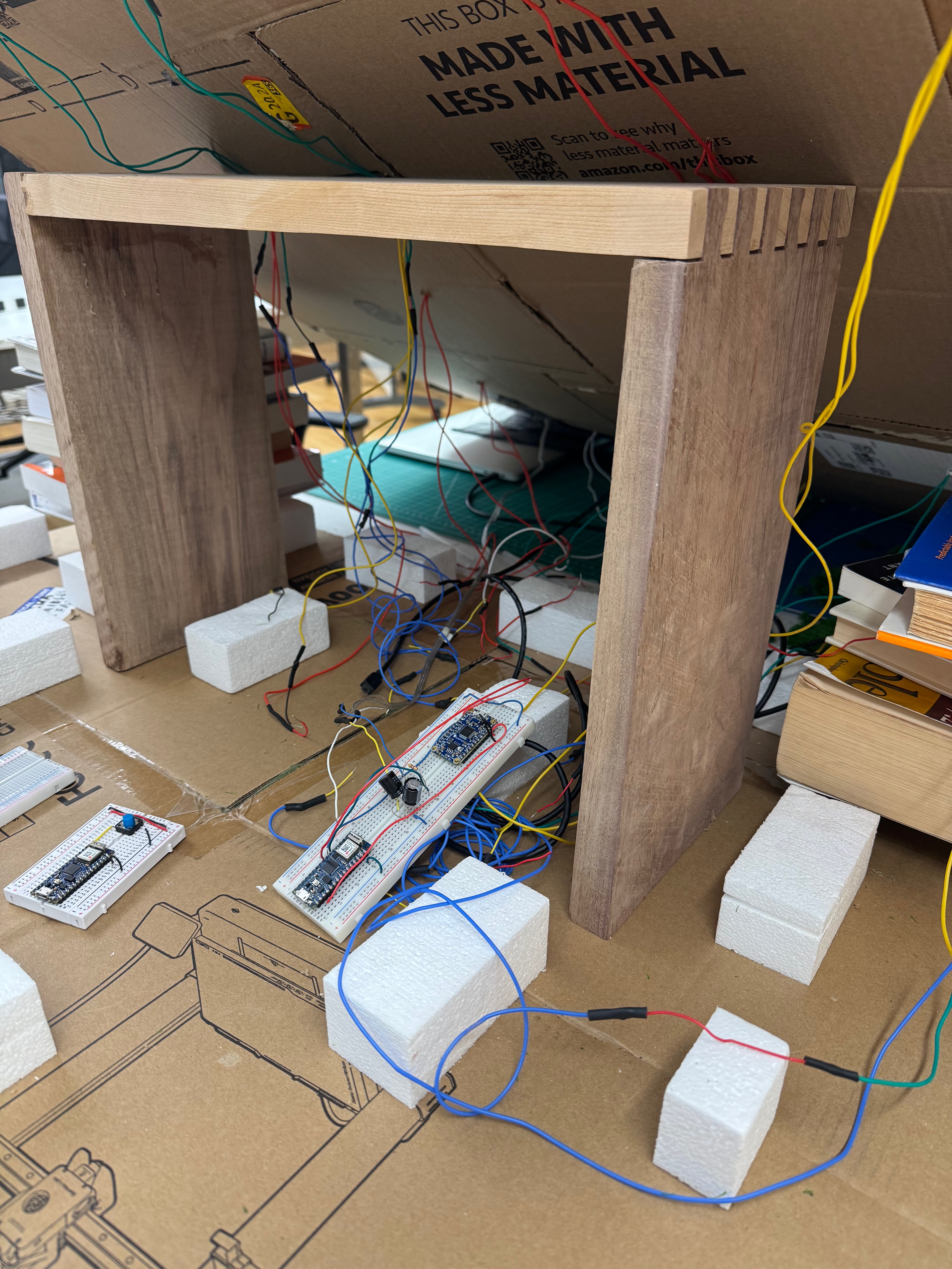
12/8 wiring all the switches, fabricating the moss garden.
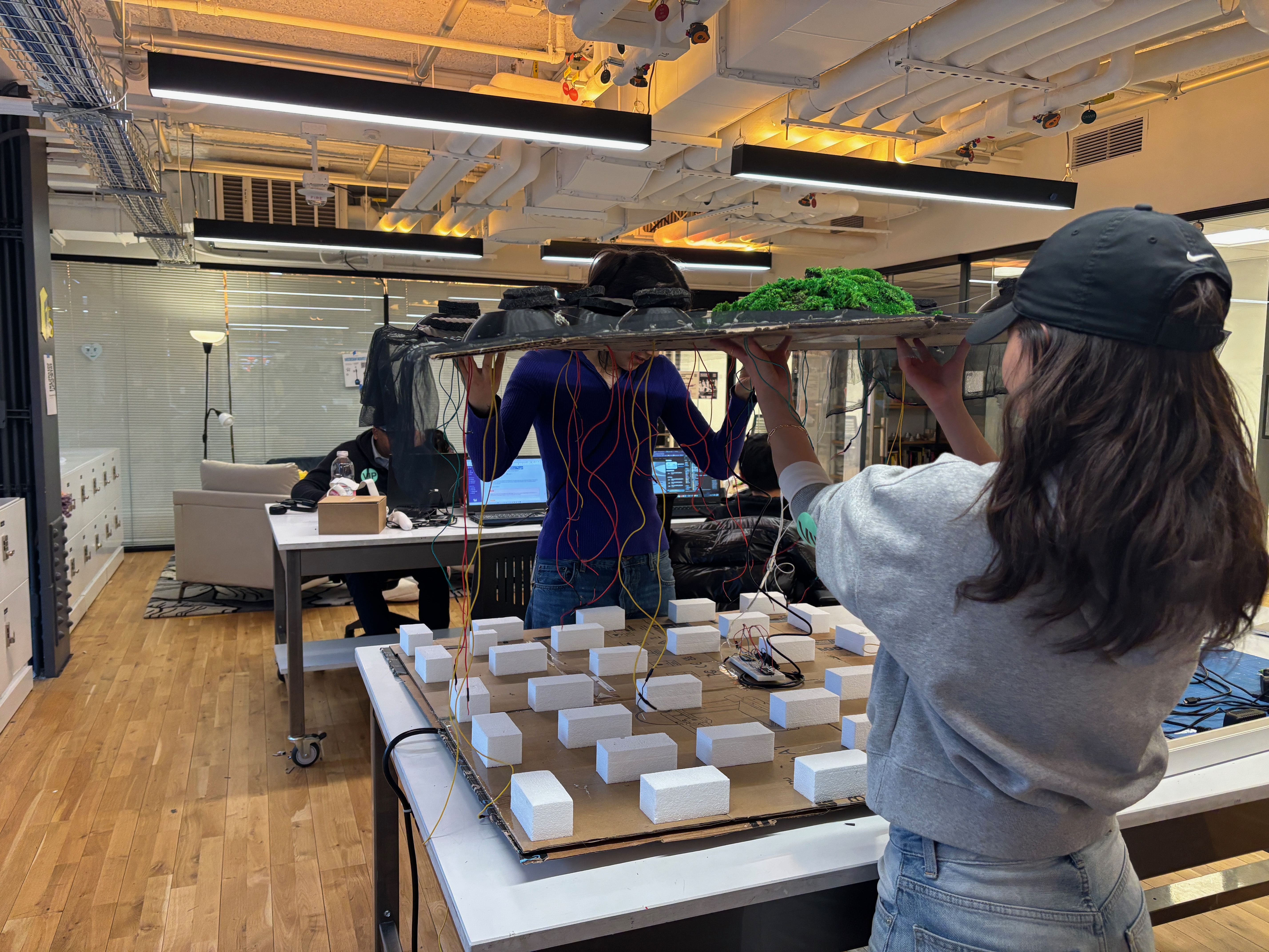
To our surprise, wiring all the switches to the breadboard ended up being the hardest part of the project.
The biggest challenge was that our physical design didn’t account for the actual wiring process. One of us had to hold the top base panel the entire time while the other person wired, which was exhausting. On top of that, the person wiring had to stay in an extremely cramped position, and it was almost impossible to see the tiny Arduino and breadboard pins hidden under the panel.
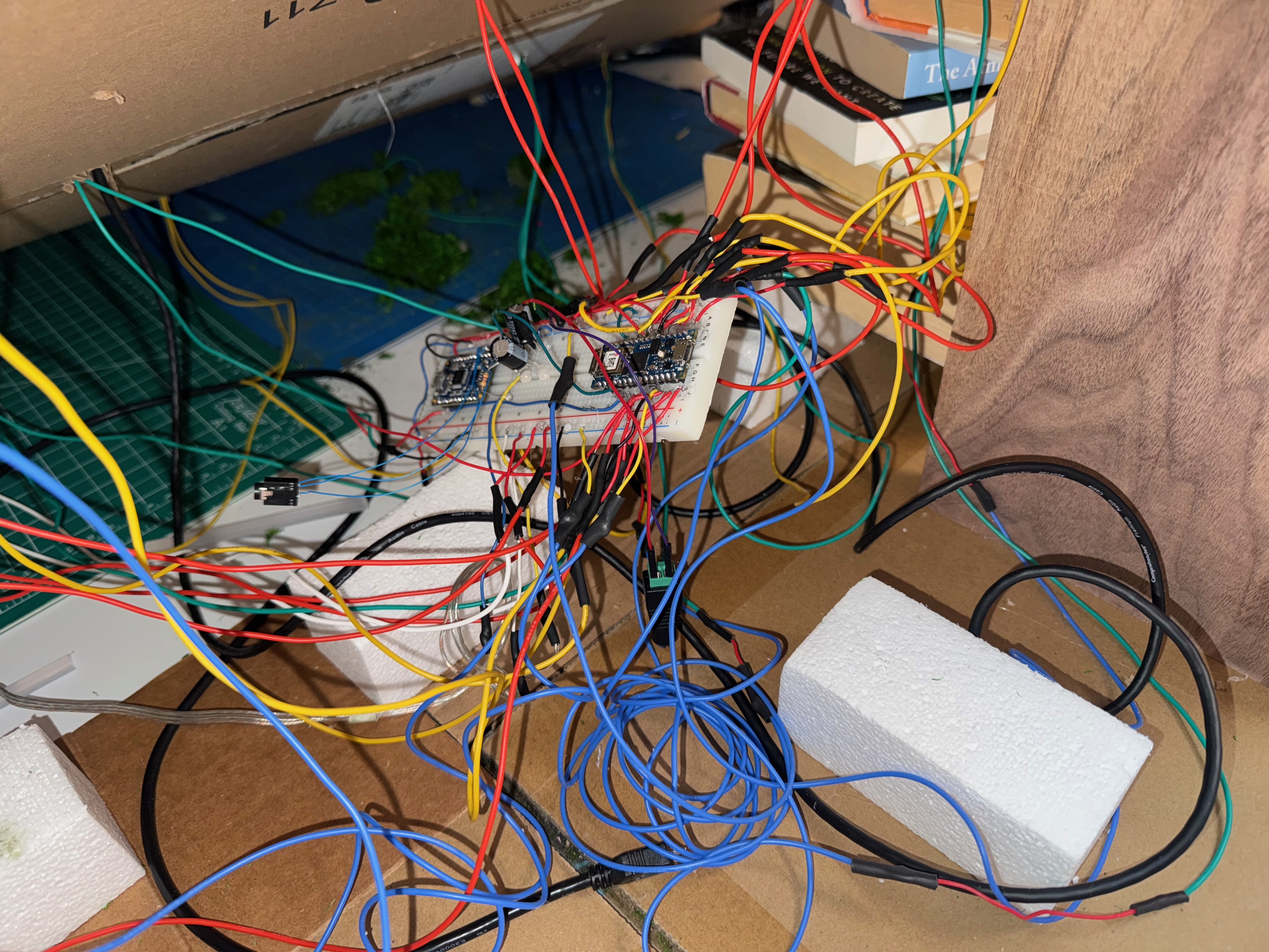
Another major difficulty was mapping the digital pins to the correct blob positions. Alua had already designed the layout, but due to several wiring issues she had to redesign everything from scratch, which meant recounting all the LED coordinates in the net — definitely not a simple task.
We also ran into smaller problems along the way: a couple of switches suddenly stopped working, so we had to remove them and revise the design again. And although we were told we could use hot glue to secure the wire connections on the breadboard, we’re pretty sure that ended up damaging the circuit, so we had to redo all the wiring on a new breadboard.
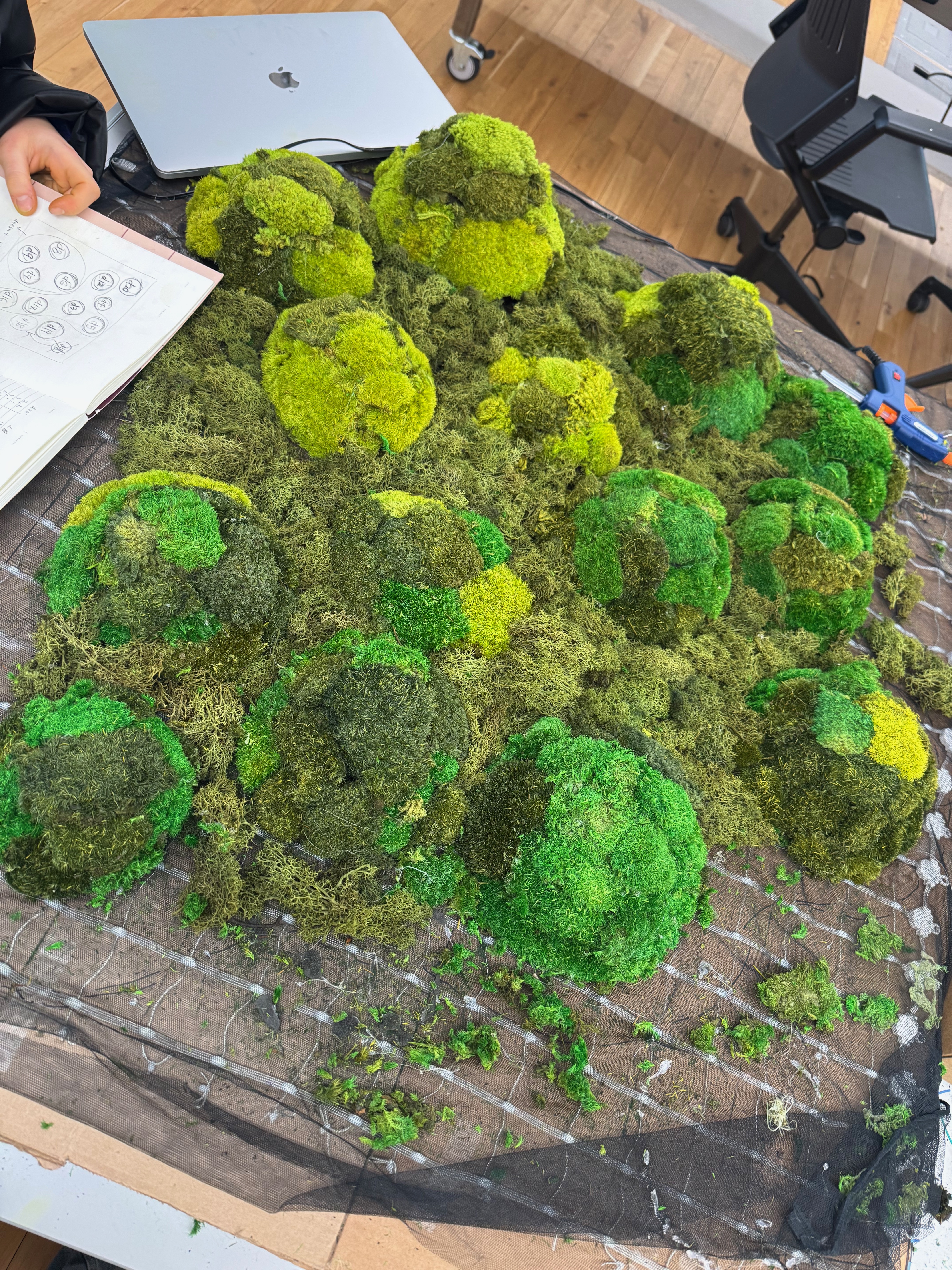
BTS , in progress of the moss designing:
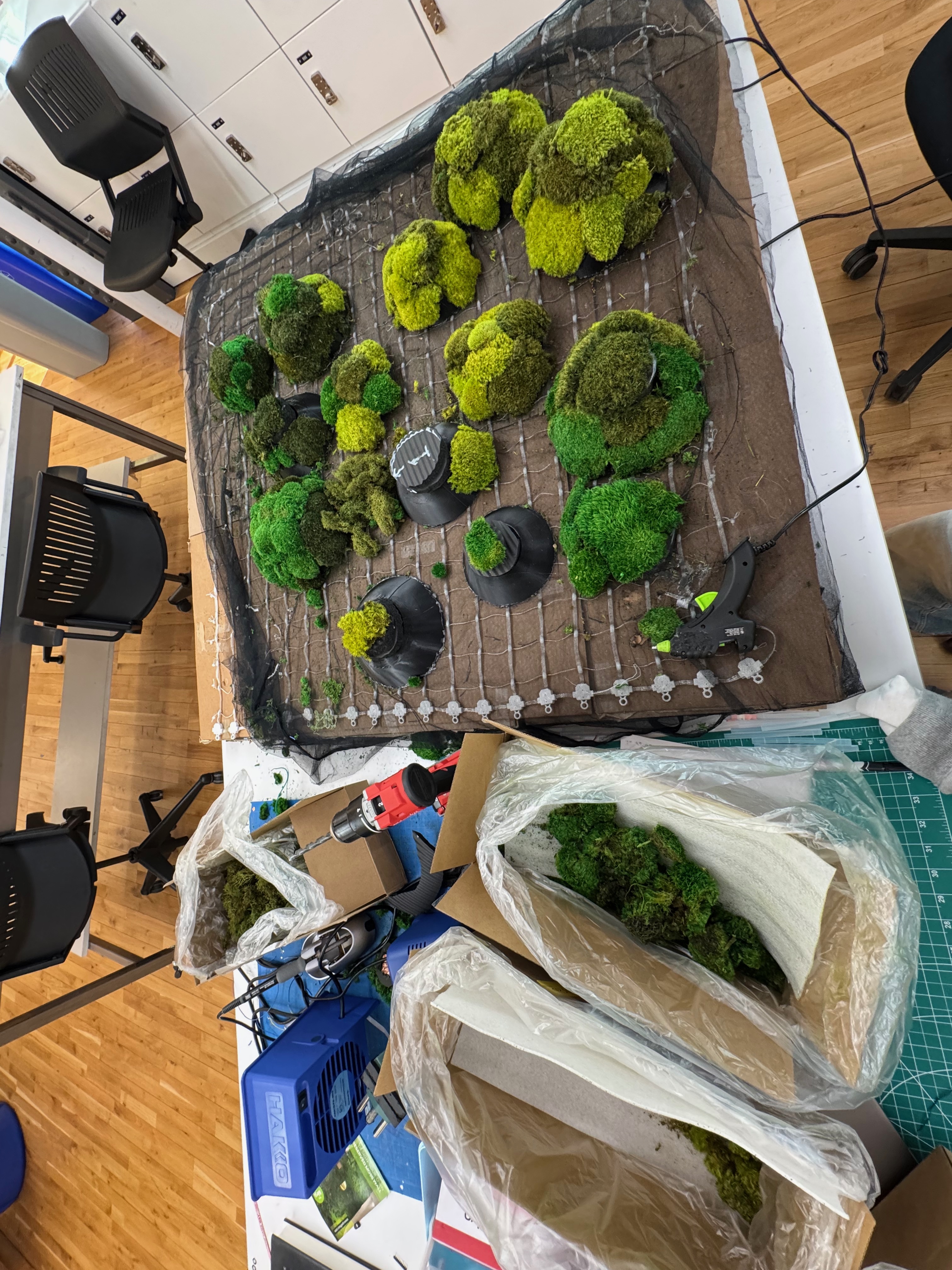
final version of moss design:
12/9 Final playtest before the show!
still need some update on :
animation code
adding sound(we already have the sound we just have to connect it to the breadboard!)
final touches on the fabrication
	cut the bottom base
	cover the side of the elevation so that inside is not shown.
	add cushions to guide the users to kneel down.
	spray water to make the moss moist, and add scent