This week, I dedicated most of my time to thoroughly reviewing all the readings and videos to fully understand the material.
Questions from the Labs this week:
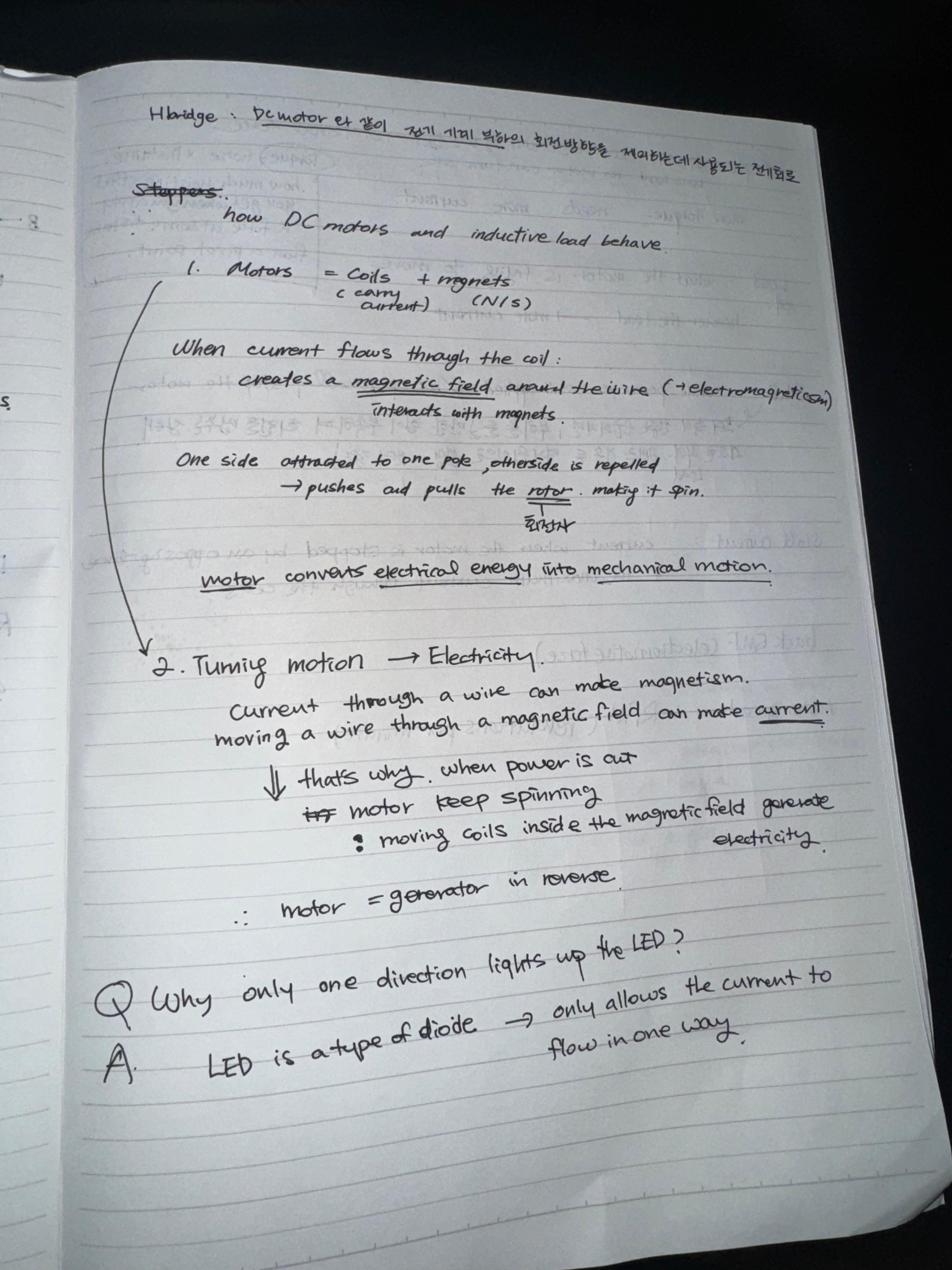
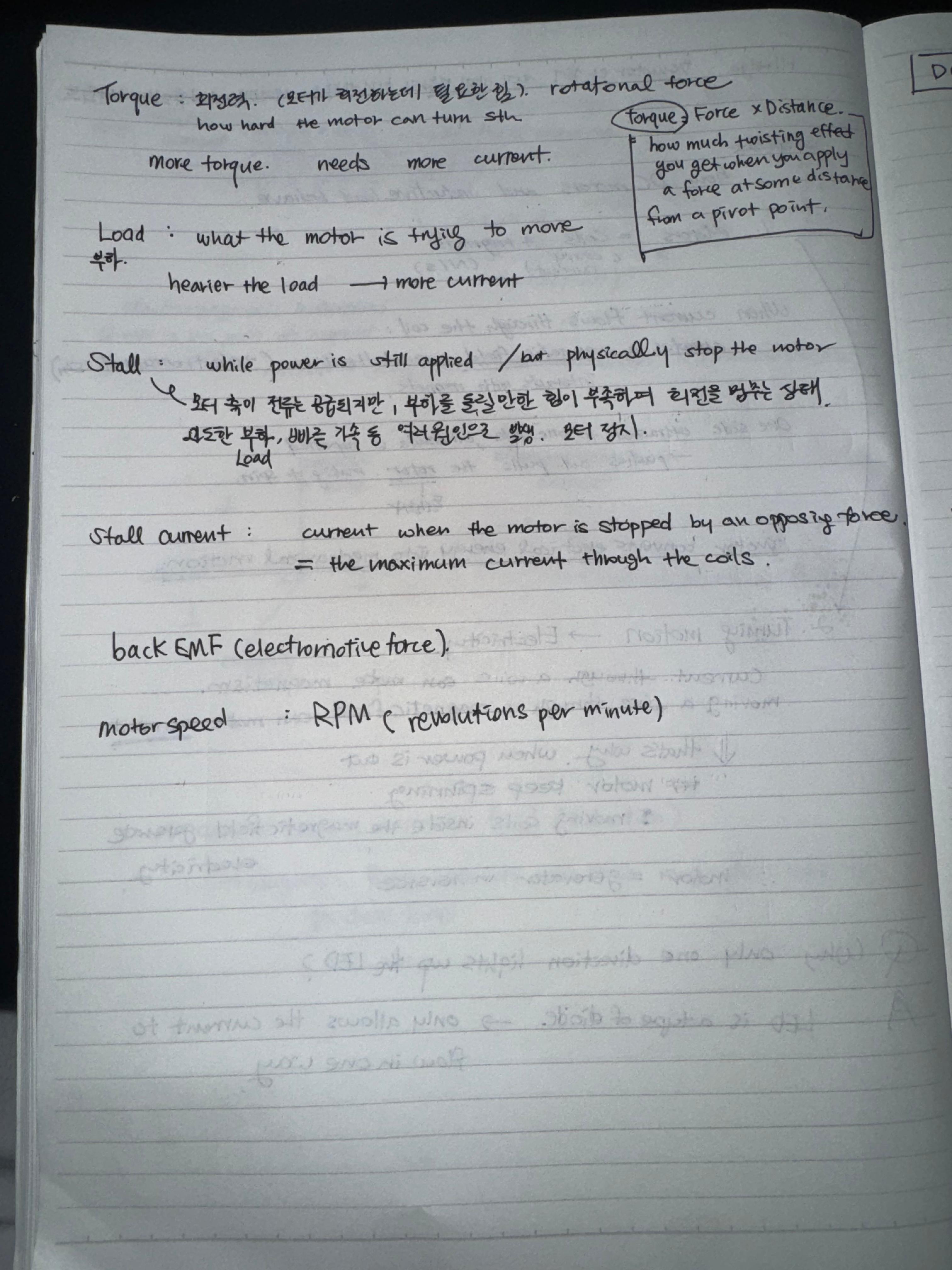
First Lab: Using a Transistor to Control High Current Loads with an Arduino
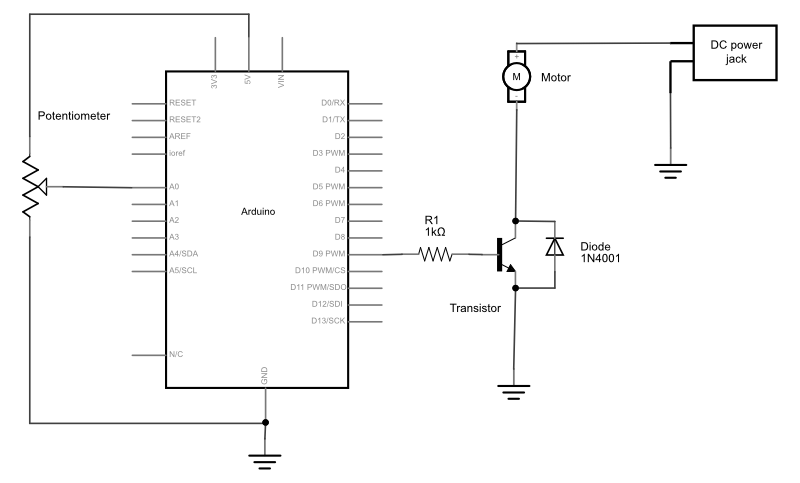
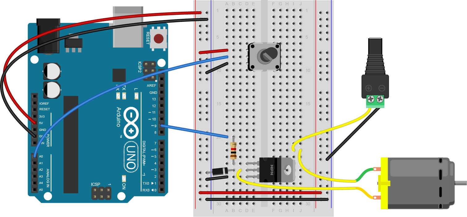 In the schematics above the diode is connecting between the collector and the emitter. but the breadboard image shows that it’s connecting the collector to the ground. Why is this?
oh wait i think I know. in the schematics shown above the diode is actually connecting from the collector to the ground. but isn’t the schematics confusing..? i think it also makes sense to read it as the diode is connected between the collector and the emitter. Maybe it’s just a basic knowledge to think that diode is connected to ground that we never get mistaken.
 I’m not sure if this sounds about right. the motor is turning on and off but the sound is going crazy,,,,
const int transistorPin = 9; // connected to the base of the transistor
void setup() {
// set the transistor pin as output:
pinMode(transistorPin, OUTPUT);
}
void loop() {
digitalWrite(transistorPin, HIGH);
delay(1000);
digitalWrite(transistorPin, LOW);
delay(1000);
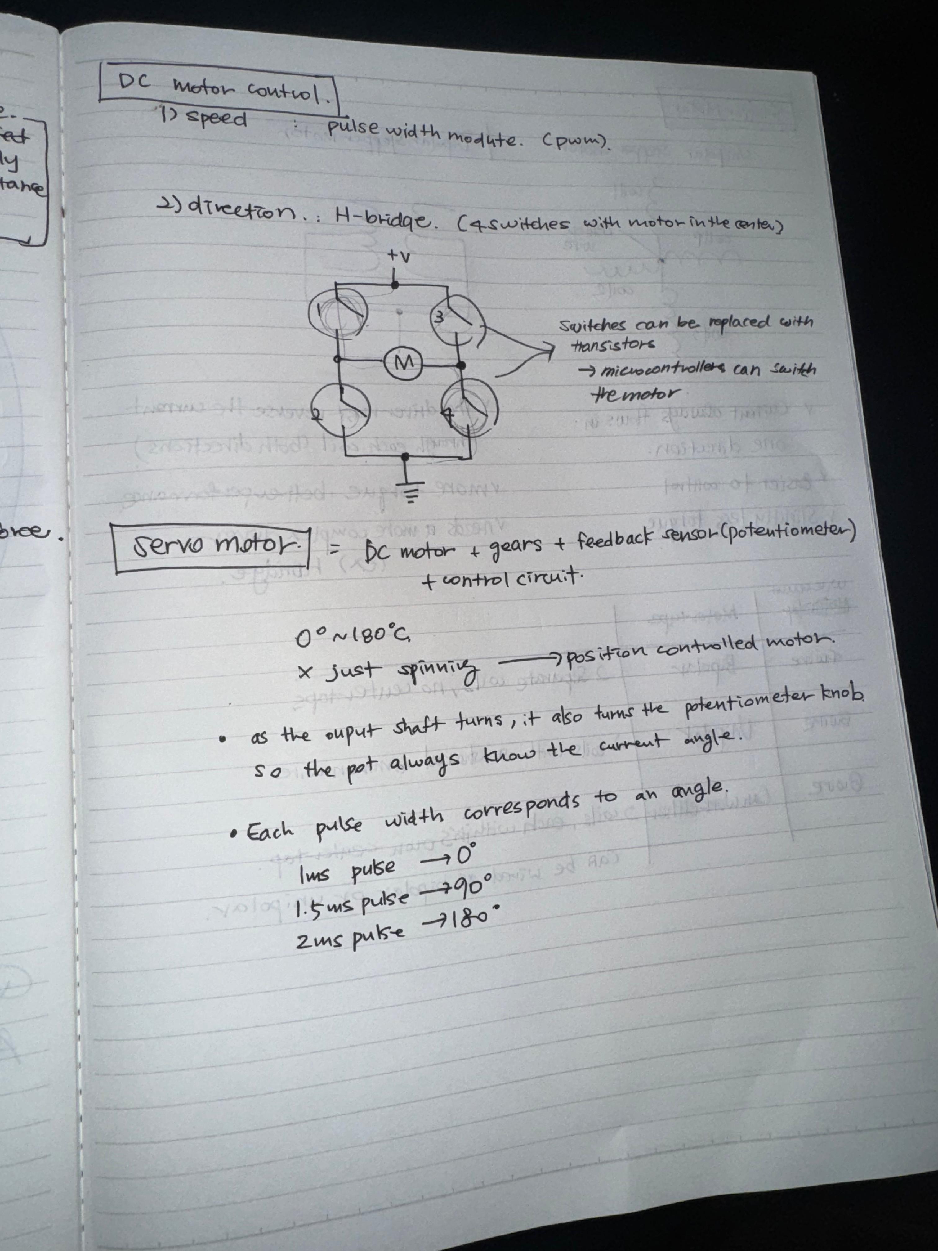
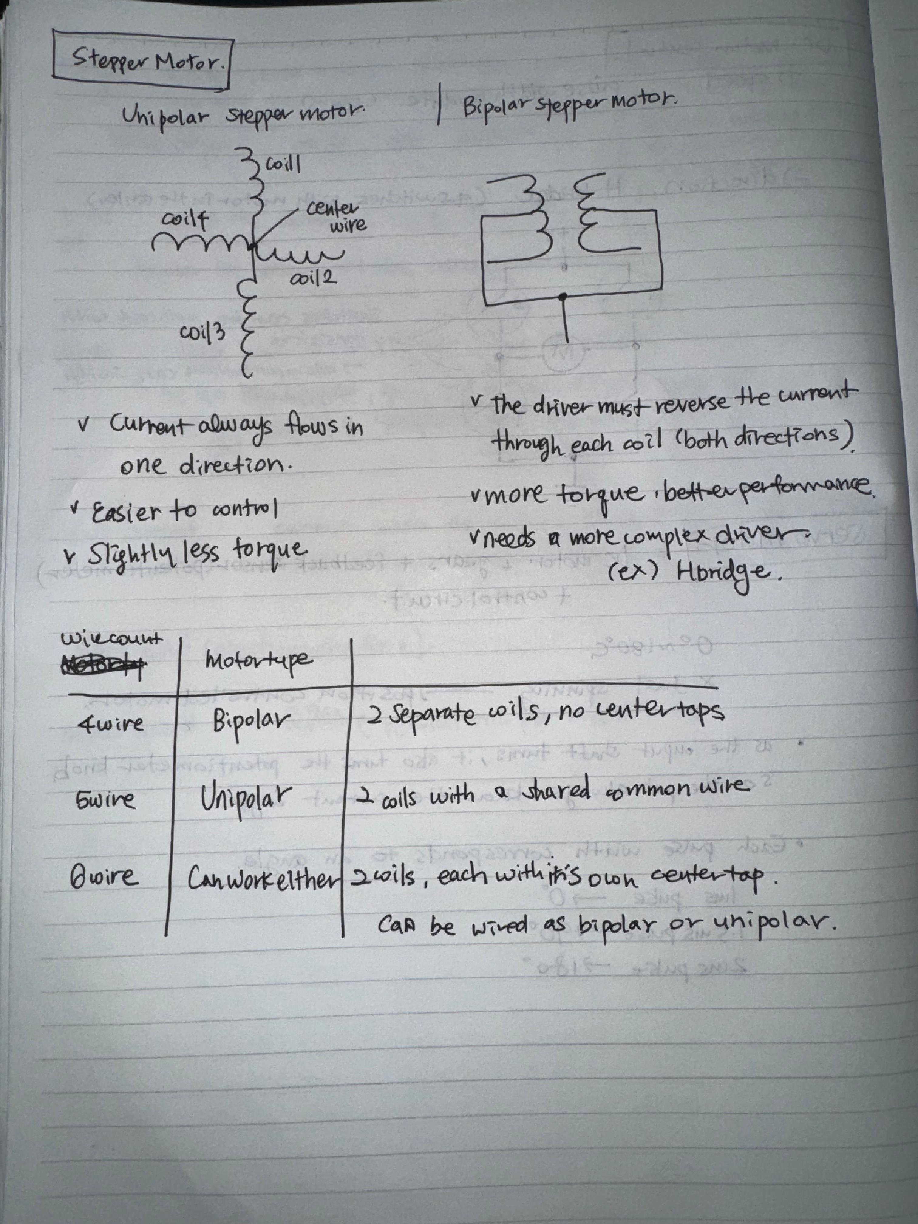
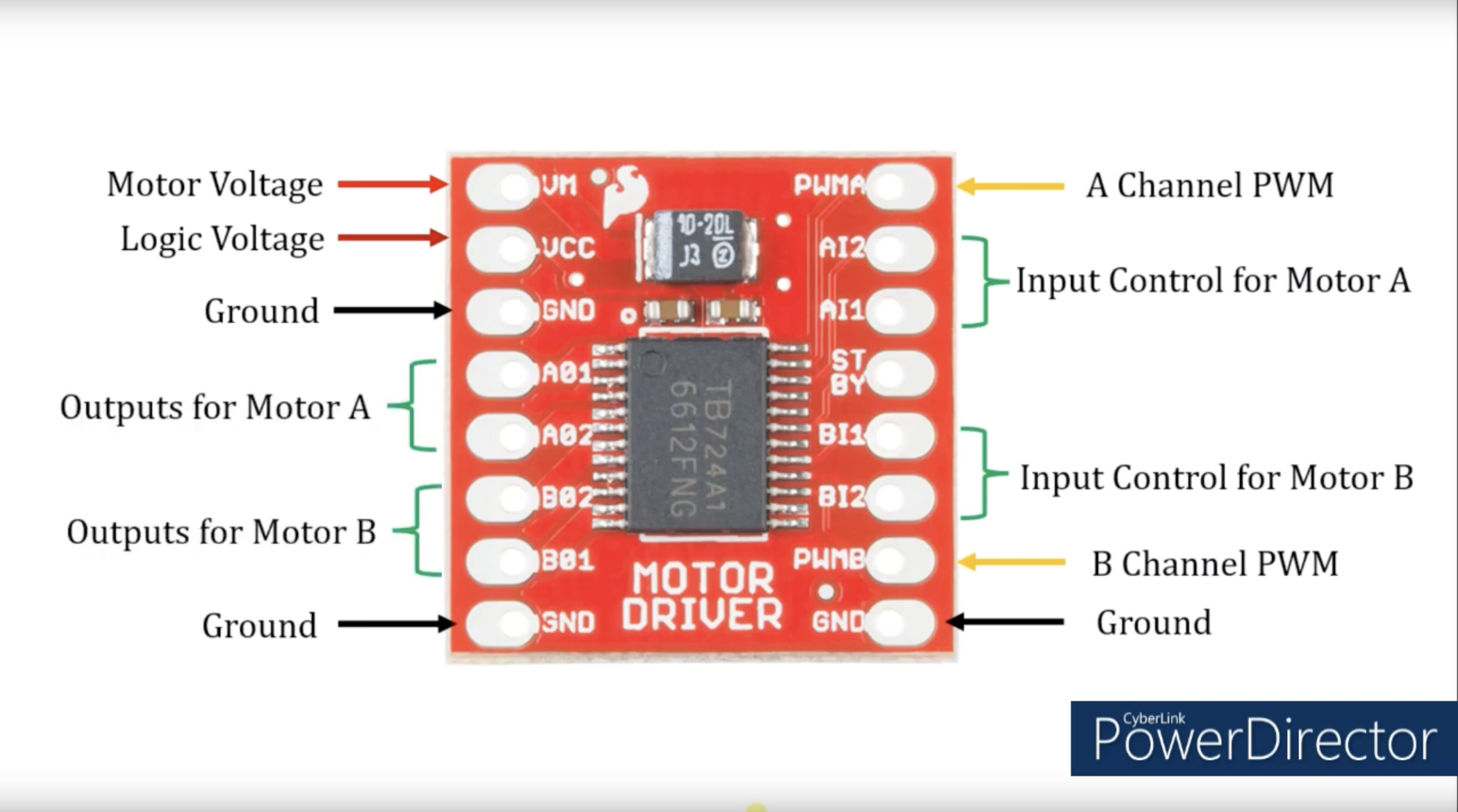
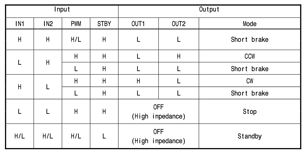
}Second Lab: DC Motor Control Using an H-Bridge
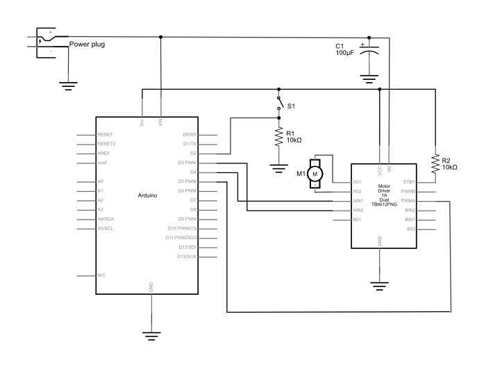
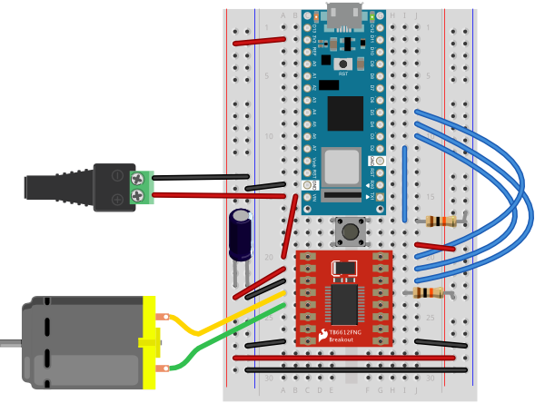
I connected all the wires but I couldn’t understand what was going on .. so I asked Arjun.
const int switchPin = 2;    // switch input
const int motor1Pin = 3;    // Motor driver leg 1 (pin 3, AIN1)
const int motor2Pin = 4;    // Motor driver leg 2 (pin 4, AIN2)
const int pwmPin = 5;       // Motor driver PWM pin

void setup() {
    // set the switch as an input:
    pinMode(switchPin, INPUT);

    // set all the other pins you're using as outputs:
    pinMode(motor1Pin, OUTPUT);
    pinMode(motor2Pin, OUTPUT);
    pinMode(pwmPin, OUTPUT);

    // set PWM enable pin high so that motor can turn on:
    digitalWrite(pwmPin, HIGH);
  }

  void loop() {
    // if the switch is high, motor will turn on one direction:
    if (digitalRead(switchPin) == HIGH) {
      digitalWrite(motor1Pin, LOW);   // set leg 1 of the motor driver low
      digitalWrite(motor2Pin, HIGH);  // set leg 2 of the motor driver high
    }
    // if the switch is low, motor will turn in the other direction:
    else {
      digitalWrite(motor1Pin, HIGH);  // set leg 1 of the motor driver high
      digitalWrite(motor2Pin, LOW);   // set leg 2 of the motor driver low
    }
  }
Timelapse of Arjun explaining how this circuit works with motor.
Below are the materials that we looked at from arjun’s blog post. Thank you Arjun.
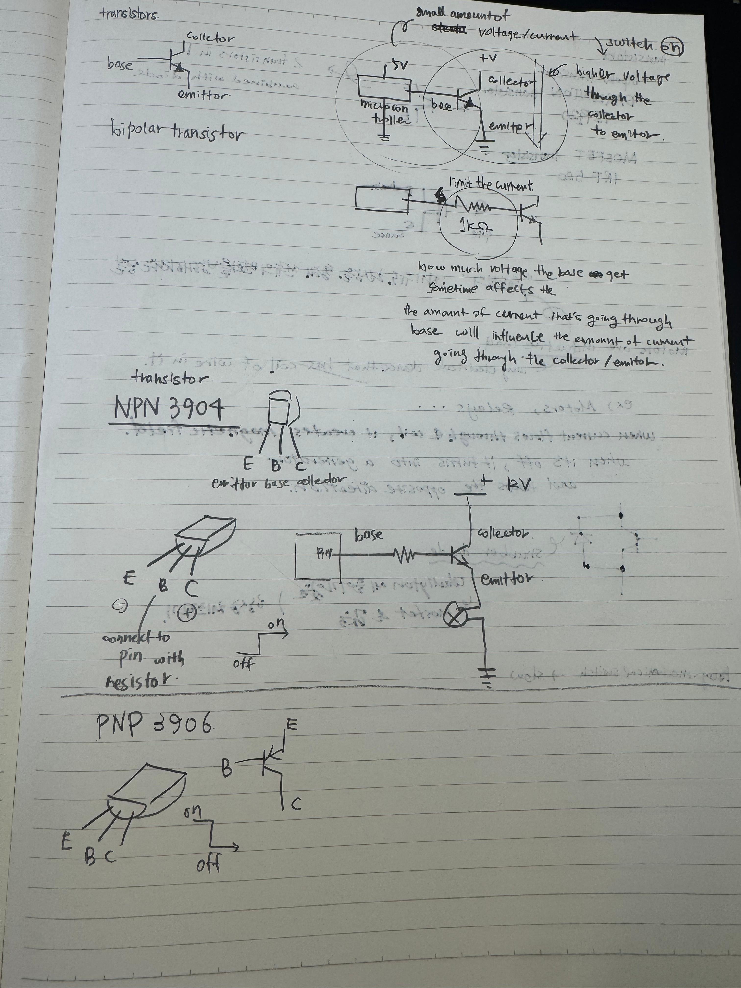
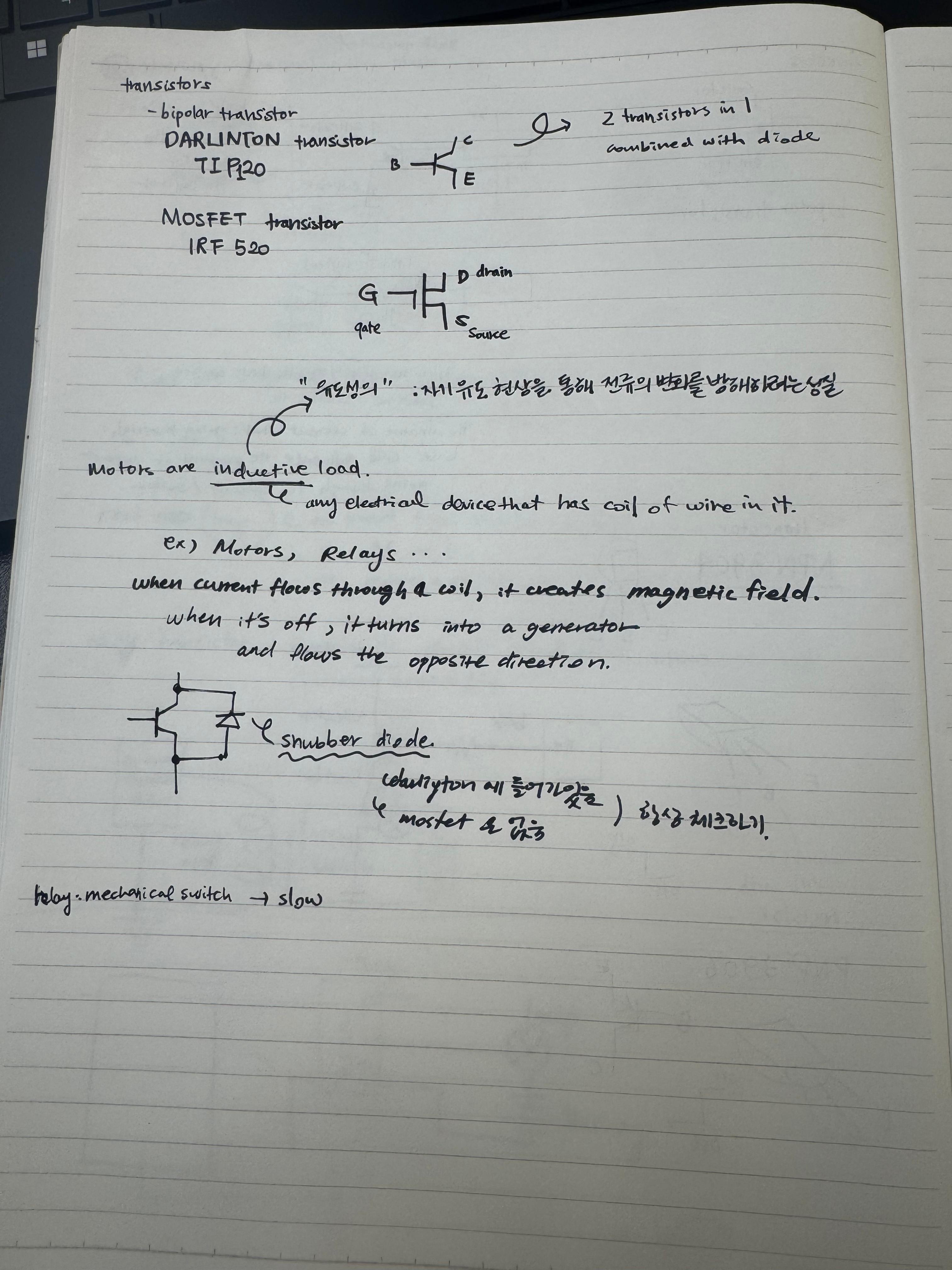
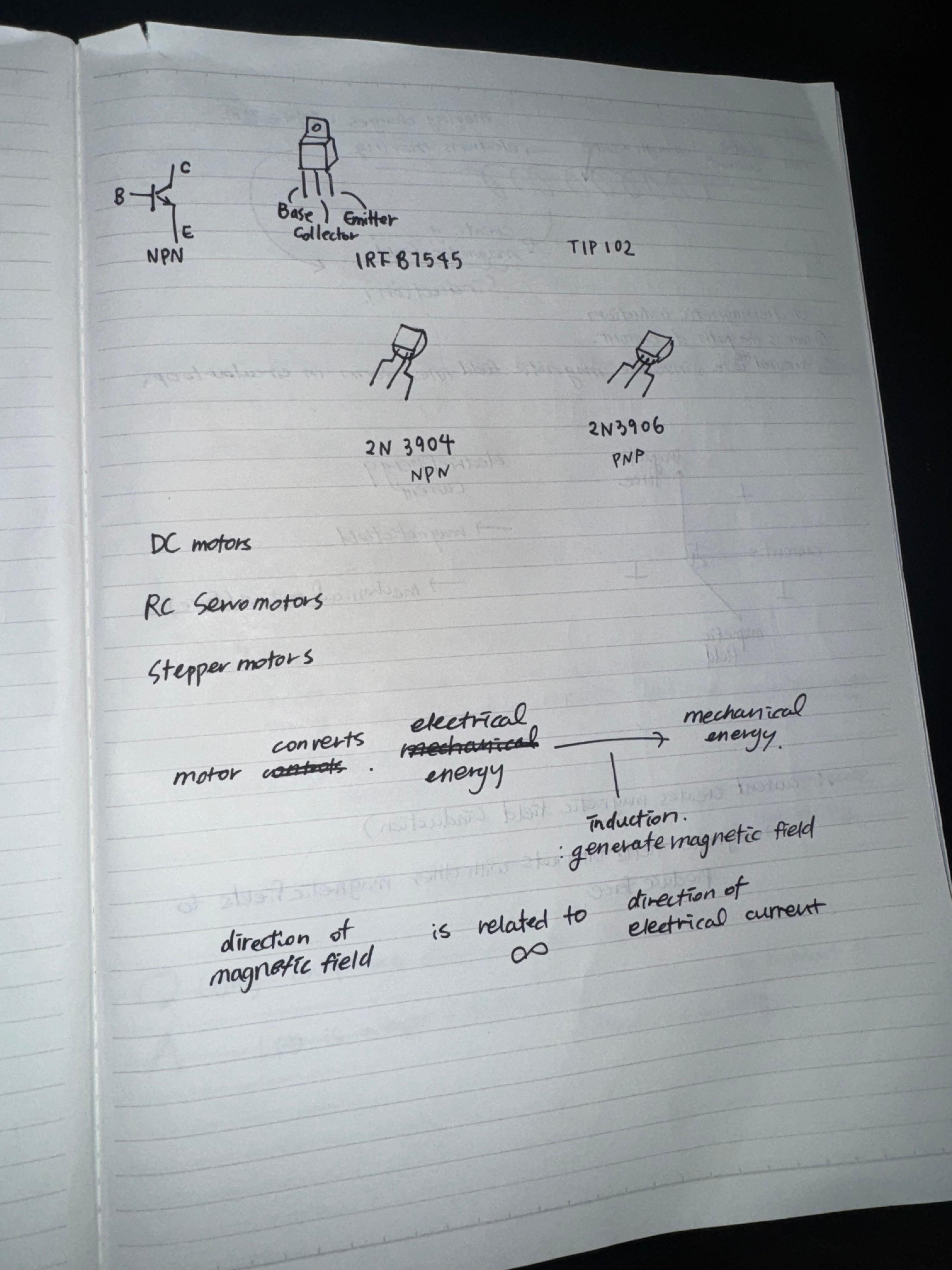
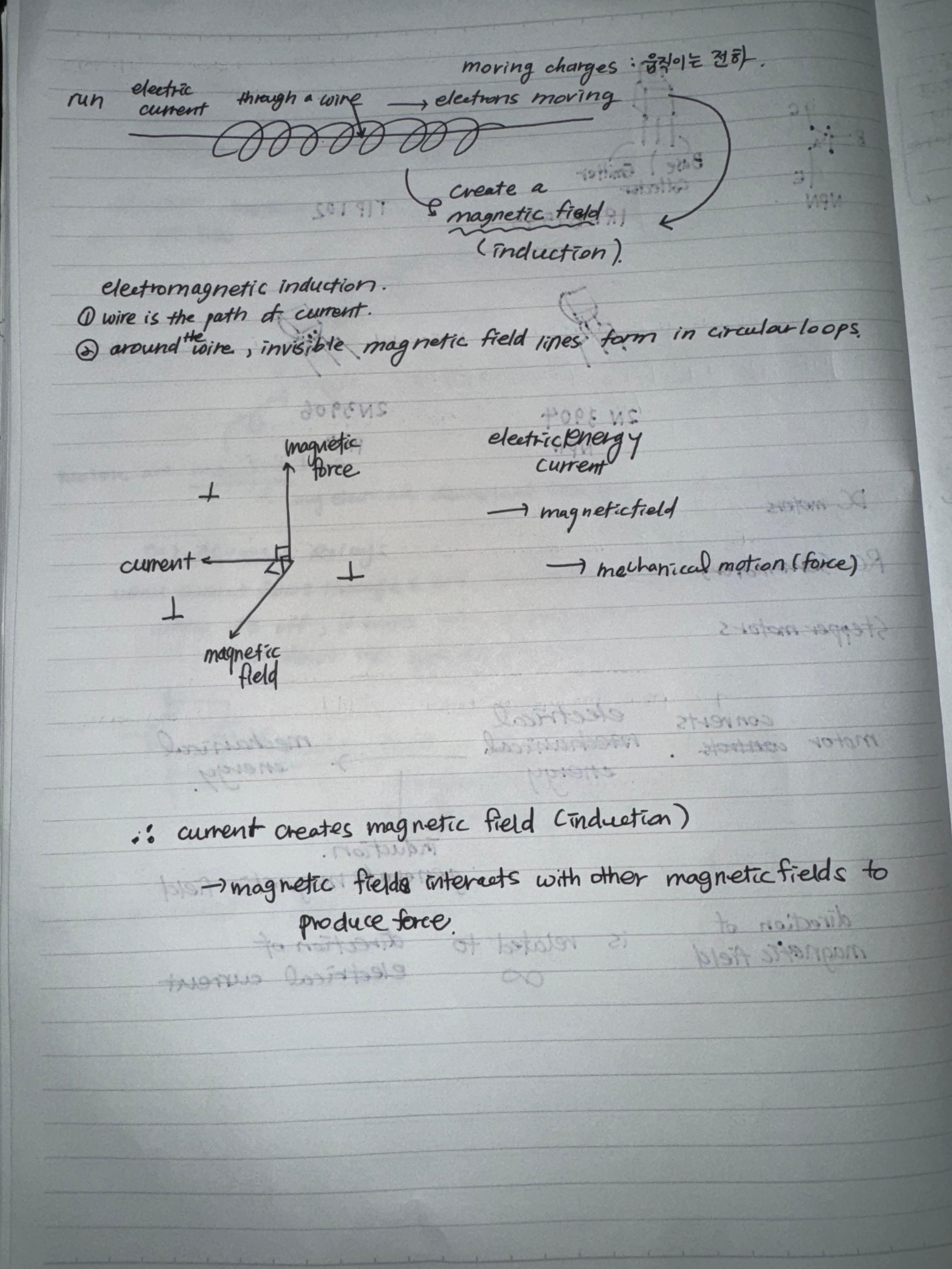
I explained to Sophia how transistors work and how they accelerate the Voltage.