For my midterm, I’m making a blank die that talks.
It’s inspired by the Magic 8 Ball and decision dice — but with a twist. Unlike normal dice covered with numbers or dots which are made for people who can see, this one has nothing on its faces.
The idea is that whether you have vision or not, everyone gets the result together. You ask a question, roll the die, and when it settles, it responds with sound instead of visuals.
The idea came from thinking about accessibility in play and interaction design — how to make something as simple as rolling a die feel fair, shared, and a little bit magical for everyone in the room.
The sound answers that I’m thinking of: Only time will tell. You already know. Ask again when you’re ready. Wait and see. Patience will reveal the truth. It’s not the right moment.
Conversation with David Rios
I talked with David Rios to get a sense of how to start my project — what to research first, what tools to learn, and how to plan the overall workflow. I wasn’t sure how to approach this project from start to finish, so I asked him to help me map out a general pipeline.
What to Do
1. Start with the Code (Electronics)
- Learn how the IMU module works. Try simple Arduino examples to read acceleration and orientation data.
- Test whether you can detect which side of the die is facing upward.
- Figure out the code part for connecting the pre-recorded .wav file to arduino.
- Lab: Playing .WAV Files from an Arduino using I2S and SPI
2. Prototype the Form
- Use cardboard boxes or Styrofoam to create quick, lightweight prototypes.
- Check whether rolling the die actually gives readable IMU data and stable orientation detection.
- This helps confirm that the sensing logic is reliable before moving into fabrication.
3. Move on to Fabrication
Once the electronics and sensing logic are proven:
- Mounting and structure:
- Figure out how to fix the Arduino, speaker, and battery securely inside the die.
- Look up “standoffs” for mounting, and check Arduino hole size (M2.5 or M3 screws).
- Power:
- Decide on the power source — 9V battery.
- The battery connects to the VIN pin on the Arduino.
- Wiring:
- Plan how to connect everything neatly. Consider using a solderable breadboard (perfboard) for stability.
- **Speaker:
- play sound in p5js
- serial communication btw p5 and arduino(usb plug)
- play 6 diff tones first instead of .wav file
- wav file or Bluetooth
- **3D Printing
- figure out 3D Modeling in Blender for 3D print
10/8 tom's office hour
1. understand the code structure with a simple output like playing diff tone for 6 faces.
2. and then you can decide if you want to do either
	1. play .wav file from the speaker inside the die
	2. play sound from the computer with bluetooth connection
3. make a prototype with cardboard and figure out the fabrication first
4. and then figure out finalizing the product like 3D printing
“This project itself is enough to considered as a Final Project. so don’t be too harsh on yourself to think that I should make it into a final product for the Midterm. just putting things together in a prototype cardboard box with all the elements working well is good.” Tom
//Unfinished code! from Tom's office hour.
//this is the overall structure that I should start with.
void setup() {
// put your setup code here, to run once:
}
void loop() {
// put your main code here, to run repeatedly:
// readSensor will return a value 0-5:
int orientation = readSensor();
// play the sound:
playSound(orientation);
}
int readSensor() {
int result;
// calculate result
return result;
}
void playSound(int whichSound) {
String sounds = { "sound1", "sound2", "sound3", "sound4", "sound5", "sound6" };
// get the filename based on the number:
// play the sound:
.play(sounds[whichSound]);
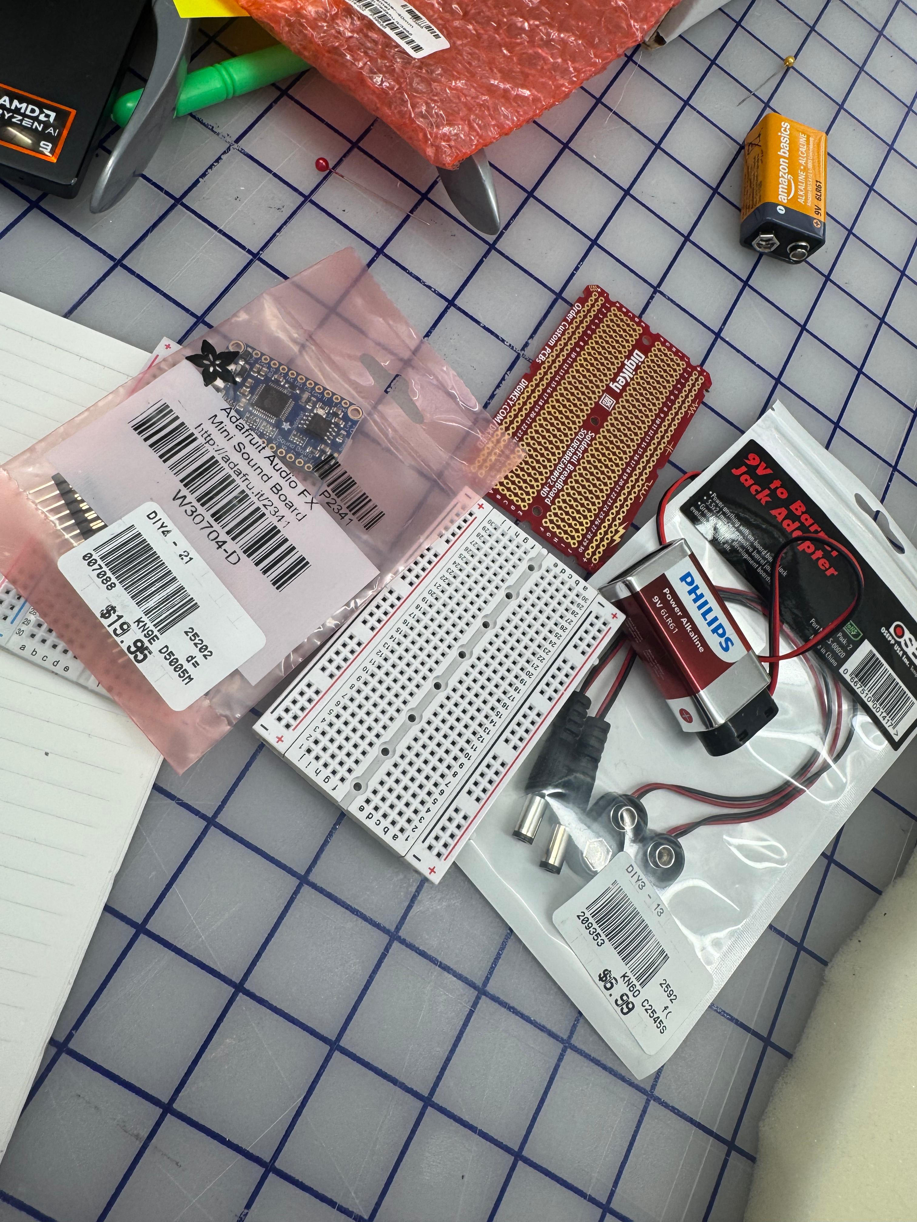
}**Things to buy
- Bread board mini
- Solderable breadboard -got it from the shop
- Batteries (which one?)
- battery adapter
- Speakers (which one?)
- standoffs (which one?)
- (anything else?)
10/6/2025 - understanding IMU Module
1)
Accessing Accelerometer Data on Nano 33 IoT
IMU stands for: inertial measurement unit.
IMU is an electronic device that measures and reports a body’s specific force, angular rate and the orientation of the body, using a combination of accelerometers(가속도계), gyroscopes(회전), and oftentimes magnetometers.(자기장측정장치). it’s a 3D digital linear acceleration sensor and a 3D digital angular rate sensor
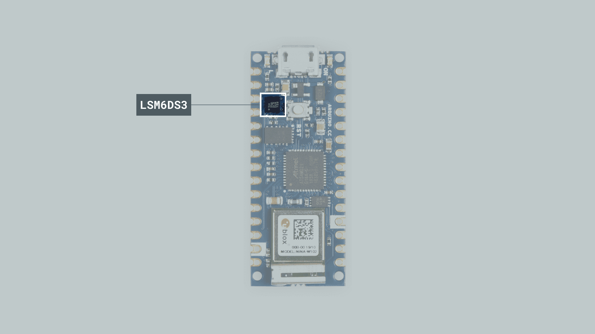
Accelerometer
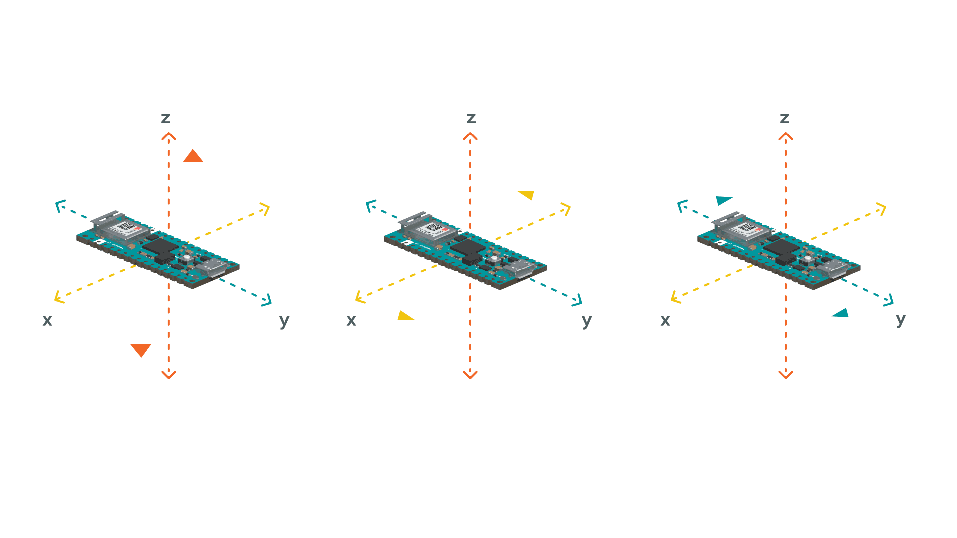 By using the accelerometer as a “level” that will provide information about the position of the board, we will be able to read what the relative position of the board is, as well as the degrees by tilting the board up, down, left or right.
#include <Arduino_LSM6DS3.h>
float x, y, z;
int degreesX = 0;
int degreesY = 0;

void setup() {
  Serial.begin(9600);
  while (!Serial);
  Serial.println("Started");

  if (!IMU.begin()) {
    Serial.println("Failed to initialize IMU!");

    while (1);
  }

  Serial.print("Accelerometer sample rate = ");
  Serial.print(IMU.accelerationSampleRate());
  Serial.println(" Hz");

}

void loop() {


  if (IMU.accelerationAvailable()) {
    IMU.readAcceleration(x, y, z);

if(x > 0.1){
    x = 100*x;
    degreesX = map(x, 0, 97, 0, 90);
    Serial.print("Tilting up ");
    Serial.print(degreesX);
    Serial.println("  degrees");
    }

  if(x < -0.1){
    x = 100*x;
    degreesX = map(x, 0, -100, 0, 90);
    Serial.print("Tilting down ");
    Serial.print(degreesX);
    Serial.println("  degrees");
    }

  if(y > 0.1){
    y = 100*y;
    degreesY = map(y, 0, 97, 0, 90);
    Serial.print("Tilting left ");
    Serial.print(degreesY);
    Serial.println("  degrees");
    }

  if(y < -0.1){
    y = 100*y;
    degreesY = map(y, 0, -100, 0, 90);
    Serial.print("Tilting right ");
    Serial.print(degreesY);
    Serial.println("  degrees");
    }
 delay(1000);
  }
}
2) accelerometer orientation
This is the code that I got from Tom Igoe https://github.com/tigoe/SensorExamples/blob/main/Accelerometers/Arduino_LSM6DS3/AccelOrientation/AccelOrientation.ino
This code reads data from an accelerometer (a sensor that detects which way is “down” due to gravity) and figures out which way your Arduino board is oriented. It only prints the orientation when it’s been stable for a while, so quick movements don’t cause confusing output.
This code makes more sense for this project!
/*
  Arduino LSM6DS3 orientation

  only prints out the accelerometer orientation if it is stable.
  avoids the problem of having to move through adjacent orientations,
  e.g. left -> top -> right. Instead, it will just print left -> right,
  if you move fast enough.

  created 29 Apr 2020
  by Tom Igoe

*/

#include <Arduino_LSM6DS3.h> //This line tells Arduino to include code that someone else wrote for talking to the LSM6DS3 sensor (the accelerometer chip). Think of it like importing a toolbox!

int lastOrientation = -1; // previous orientation of the accelerometer = stores what orientation we saw last time (starts at -1, meaning "no orientation yet")
int sameReading = 0;      // how many times you've gotten the same reading
int threshold = 7;        // how many same readings make the reading stable = the magic number (7) - we need 7 identical readings before we trust it's stable

void setup() { // void means this function doesn't return any value - it just does stuff.
  // initialize serial communication:
  Serial.begin(9600); //This starts **serial communication** at 9600 baud (speed). Serial lets your Arduino send text messages to your computer so you can see what's happening!

  // start the IMU:
  if (!IMU.begin()) { //= "if the IMU fails to start..."
    Serial.println("Failed to initialize IMU!");
    while (true); //= infinite loop that does nothing - this stops the program if the sensor isn't working
  }
}

void loop() {
  // variables for accelerometer readings:
  float x, y, z; //= will store the acceleration in three directions (3D space!)
  // variable for orientation:
  int orientation = -1; //= will store which way the board is facing (0-5, or -1 for "unknown")

  // if the accelerometer's got readings,
  if (IMU.accelerationAvailable()) {
    // This checks: "Does the sensor have new data ready for us?" If yes, we go inside the `if` block.
    IMU.readAcceleration(x, y, z);

    // This reads the sensor and puts the values into our `x`, `y`, `z` variables. These values show how much acceleration (gravity) is pulling in each direction. Values are typically between -1.0 and 1.0.

For example, if the board is flat on a table with the top facing up, `z` will be close to 1.0 (gravity pulling down through the Z-axis).

//`abs()` = absolute value (removes negative signs). We want to know which axis has the **strongest** pull, regardless of direction. Example: `abs(-0.98)` = `0.98`
    int absX = abs(x);
    int absY = abs(y);
    int absZ = abs(z);

    // if Z  is greatest, we must be on the Z axis:
    if ( (absZ > absX) && (absZ > absY)) {
      if (z > 0) {
        orientation = 0;  // Z up
      } else {
        orientation = 1;  // Z down
      }
      // if Y  is greatest, we must be on the Y axis:
    } else if ( (absY > absX) && (absY > absZ)) {

      if (y > 0) {
        // Y up:
        orientation = 2;
      } else {
        // Y down:
        orientation = 3;
      }
      // if X  is greatest, we must be on the X axis:
    } else if ( (absX > absY) && (absX > absZ)) {
      if (x < 0) {
        // X up:
        orientation = 4;
      } else {
        // X down:
        orientation = 5;
      }
    }

    // if we have a valid reading:
    if (orientation > -1 ) {
      // if the reading has been the same many times in a row,
      // then it is stable. print it:
      if (sameReading == threshold) {
        Serial.println(orientation);
        //play sound

      }

      // if the orientation has changed:
      if (orientation != lastOrientation) {
        // save the current for next time:
        lastOrientation = orientation;
        // clear sameReading:
        sameReading = 0;
      } else {
        // increment sameReading:
        sameReading++;
      }
    }
  }
}
Some more LABs that I should look into proceeding forward. :
3) Lab: Serial IMU Output to p5.js Using p5.webserial
https://itp.nyu.edu/physcomp/labs/lab-serial-imu-output-to-p5-js/
4) Lab: Playing .WAV Files from an Arduino using I2S and SPI
https://itp.nyu.edu/physcomp/lab-playing-wav-files-from-an-arduino/
5) Lab: Bluetooth LE and p5.ble
https://itp.nyu.edu/physcomp/labs/lab-bluetooth-le-and-p5-ble/
10/18/2025
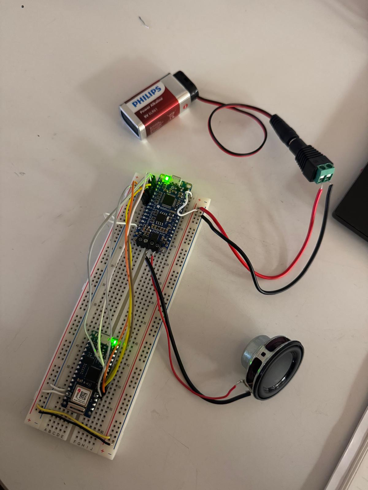
Fabri offered to use the soundboard to play the .wav file. Basically, I’m connecting the arduino to the soundboard which stores the .wav files(T00-T05).
soundboard tutorial documentation:
https://learn.adafruit.com/adafruit-audio-fx-sound-board/triggering-audio\
mystery die schematics:
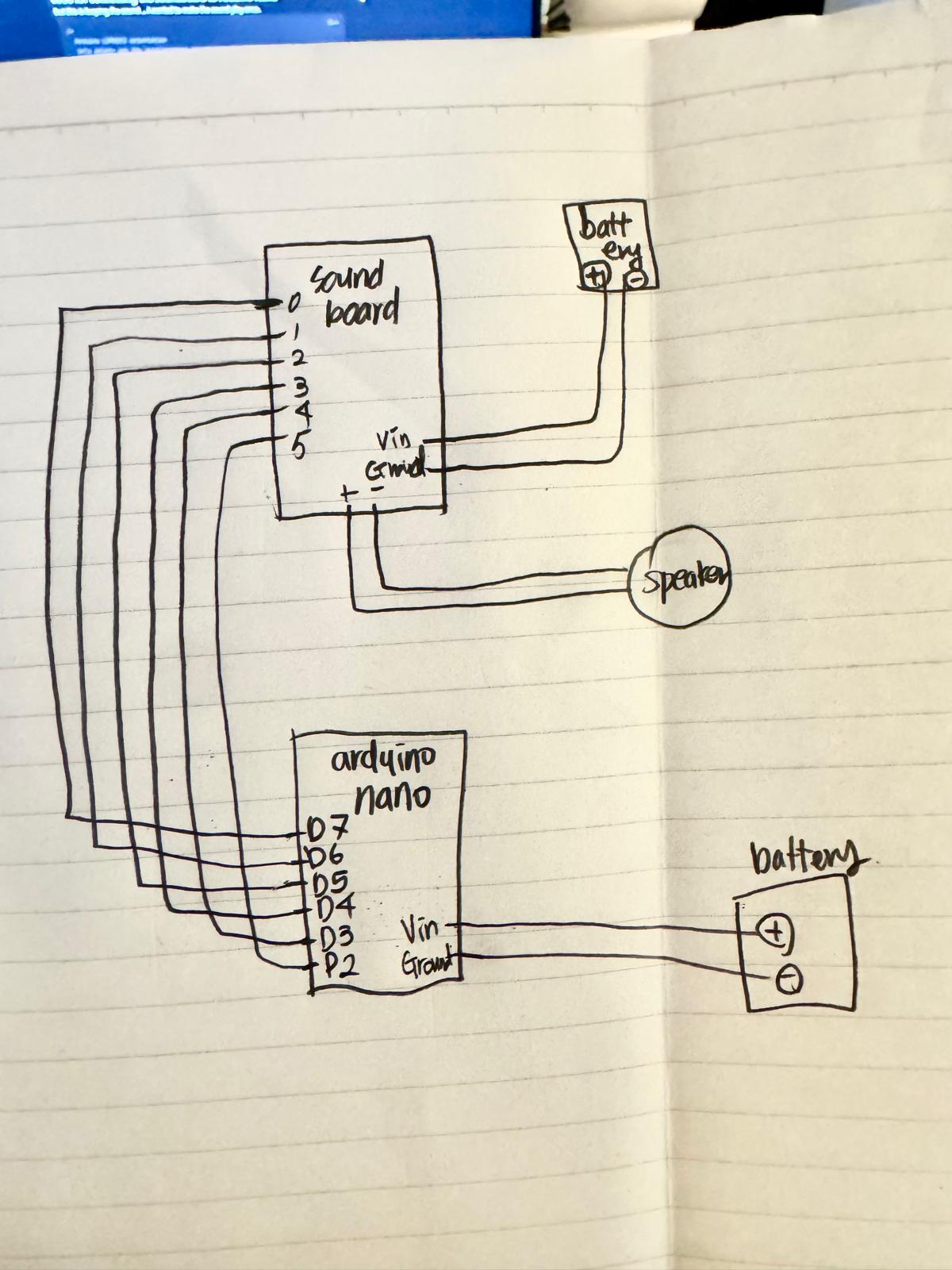
code for connecting the soundboard to Arduino Nano
but this is looping the sound … I wanted to make the sound play once.
/*
  Arduino LSM6DS3 orientation
  only prints out the accelerometer orientation if it is stable.
  Triggers Soundboard pins based on orientation.
*/
#include <Arduino_LSM6DS3.h>
int lastOrientation = -1; // previous orientation of the accelerometer
int sameReading = 0;      // how many times you've gotten the same reading
int threshold = 7;        // how many same readings make the reading stable

void setup() {
  // initialize serial communication:
  Serial.begin(9600);

  pinMode(2, OUTPUT);
  pinMode(3, OUTPUT);
  pinMode(4, OUTPUT);
  pinMode(5, OUTPUT);
  pinMode(6, OUTPUT);
  pinMode(7, OUTPUT);

  // Set all pins HIGH at startup
  digitalWrite(2, HIGH);
  digitalWrite(3, HIGH);
  digitalWrite(4, HIGH);
  digitalWrite(5, HIGH);
  digitalWrite(6, HIGH);
  digitalWrite(7, HIGH);

  // start the IMU:
  if (!IMU.begin()) {
    Serial.println("Failed to initialize IMU!");
    while (true);
  }
}

void loop() {
  // variables for accelerometer readings:
  float x, y, z;
  // variable for orientation:
  int orientation = -1;

  // if the accelerometer's got readings,
  if (IMU.accelerationAvailable()) {
    // read the accelerometer:
    IMU.readAcceleration(x, y, z);

    // calculate the absolute values, to determine the largest
    int absX = abs(x);
    int absY = abs(y);
    int absZ = abs(z);

    // if Z is greatest, we must be on the Z axis:
    if ( (absZ > absX) && (absZ > absY)) {
      if (z > 0) {
        orientation = 0;  // Z up
      } else {
        orientation = 1;  // Z down
      }
      // if Y is greatest, we must be on the Y axis:
    } else if ( (absY > absX) && (absY > absZ)) {
      if (y > 0) {
        orientation = 2;  // Y up
      } else {
        orientation = 3;  // Y down
      }
      // if X is greatest, we must be on the X axis:
    } else if ( (absX > absY) && (absX > absZ)) {
      if (x < 0) {
        orientation = 4;  // X up
      } else {
        orientation = 5;  // X down
      }
    }

    // if we have a valid reading:
    if (orientation > -1) {
      // if the reading has been the same many times in a row,
      // then it is stable:
      if (sameReading == threshold) {
        Serial.println(orientation);
      }

      // if the orientation has changed:
      if (orientation != lastOrientation) {
        // Turn OFF all pins first
        digitalWrite(2, HIGH);
        digitalWrite(3, HIGH);
        digitalWrite(4, HIGH);
        digitalWrite(5, HIGH);
        digitalWrite(6, HIGH);
        digitalWrite(7, HIGH);

        delay(50);  // Small delay between turning off and turning on

        // Turn ON the pin for current orientation
        digitalWrite(orientation + 2, LOW);

        // save the current for next time:
        lastOrientation = orientation;
        // clear sameReading:
        sameReading = 0;
      } else {
        // increment sameReading:
        sameReading++;
      }
    }
  }
}
this code works!! it plays only once when it figures out the side.
/*

  Arduino LSM6DS3 orientation

  only prints out the accelerometer orientation if it is stable.

  avoids the problem of having to move through adjacent orientations,

  e.g. left -> top -> right. Instead, it will just print left -> right,

  if you move fast enough.

  MODIFIED: Pins only go LOW once per stable orientation (no looping)

  created 29 Apr 2020

  by Tom Igoe

*/

#include <Arduino_LSM6DS3.h>

int lastOrientation = -1; // previous orientation of the accelerometer

int sameReading = 0;      // how many times you've gotten the same reading

int threshold = 7;        // how many same readings make the reading stable

bool pinActivated = false; // tracks if we've already activated the pin for this orientation

unsigned long pinLowTime = 0; // time when pin was set LOW

unsigned long pinHoldDuration = 300; // how long to keep pin LOW (milliseconds)


void setup() {

  // initialize serial communication:

  Serial.begin(9600);

  pinMode(2, OUTPUT);

  pinMode(3, OUTPUT);

  pinMode(4, OUTPUT);

  pinMode(5, OUTPUT);

  pinMode(6, OUTPUT);

  pinMode(7, OUTPUT);

  // start the IMU:

  if (!IMU.begin()) {

    Serial.println("Failed to initialize IMU!");

    while (true);

  }

}


void loop() {

  // Check if it's time to turn the pin back HIGH

  if (pinActivated && (millis() - pinLowTime >= pinHoldDuration)) {

    // Turn all pins back HIGH

    digitalWrite(2, HIGH);

    digitalWrite(3, HIGH);

    digitalWrite(4, HIGH);

    digitalWrite(5, HIGH);

    digitalWrite(6, HIGH);

    digitalWrite(7, HIGH);

    pinActivated = false;

  }

  // variables for accelerometer readings:

  float x, y, z;

  // variable for orientation:

  int orientation = -1;

  // if the accelerometer's got readings,

  if (IMU.accelerationAvailable()) {

    // read the accelerometer:

    IMU.readAcceleration(x, y, z);

    // calculate the absolute values, to determine the largest

    int absX = abs(x);

    int absY = abs(y);

    int absZ = abs(z);

    // if Z is greatest, we must be on the Z axis:

    if ( (absZ > absX) && (absZ > absY)) {

      if (z > 0) {

        orientation = 0;  // Z up

      } else {

        orientation = 1;  // Z down

      }

      // if Y is greatest, we must be on the Y axis:

    } else if ( (absY > absX) && (absY > absZ)) {

      if (y > 0) {

        // Y up:

        orientation = 2;

      } else {

        // Y down:

        orientation = 3;

      }

      // if X is greatest, we must be on the X axis:

    } else if ( (absX > absY) && (absX > absZ)) {

      if (x < 0) {

        // X up:

        orientation = 4;

      } else {

        // X down:

        orientation = 5;

      }

    }

    // if we have a valid reading:

    if (orientation > -1) {

      // if the orientation has changed:

      if (orientation != lastOrientation) {

        // Turn all pins HIGH first (reset them)

        digitalWrite(2, HIGH);

        digitalWrite(3, HIGH);

        digitalWrite(4, HIGH);

        digitalWrite(5, HIGH);

        digitalWrite(6, HIGH);

        digitalWrite(7, HIGH);

        // save the current for next time:

        lastOrientation = orientation;

        // clear sameReading:

        sameReading = 0;

        // reset the flag so we can activate the pin when stable

        pinActivated = false;

      } else {

        // increment sameReading:

        sameReading++;

      }

      // if the reading has been the same many times in a row, then it is stable:

      if (sameReading == threshold) {

        Serial.println(orientation);

        // Only set the pin LOW once per stable orientation

        if (!pinActivated) {

          digitalWrite(orientation + 2, LOW);

          pinLowTime = millis(); // record when we set it LOW

          pinActivated = true;

        }

      }

    }

  }

}
I wish to make the dice as small as possible so I’m going to go to Adafruit on Monday(10/20/2025) morning to get one more half size breadboard(I already have one) and one more 9V battery clip(I alrdy have one of this too) and make the dice smaller. possibly like 10 * 10 * 10cm size dice.
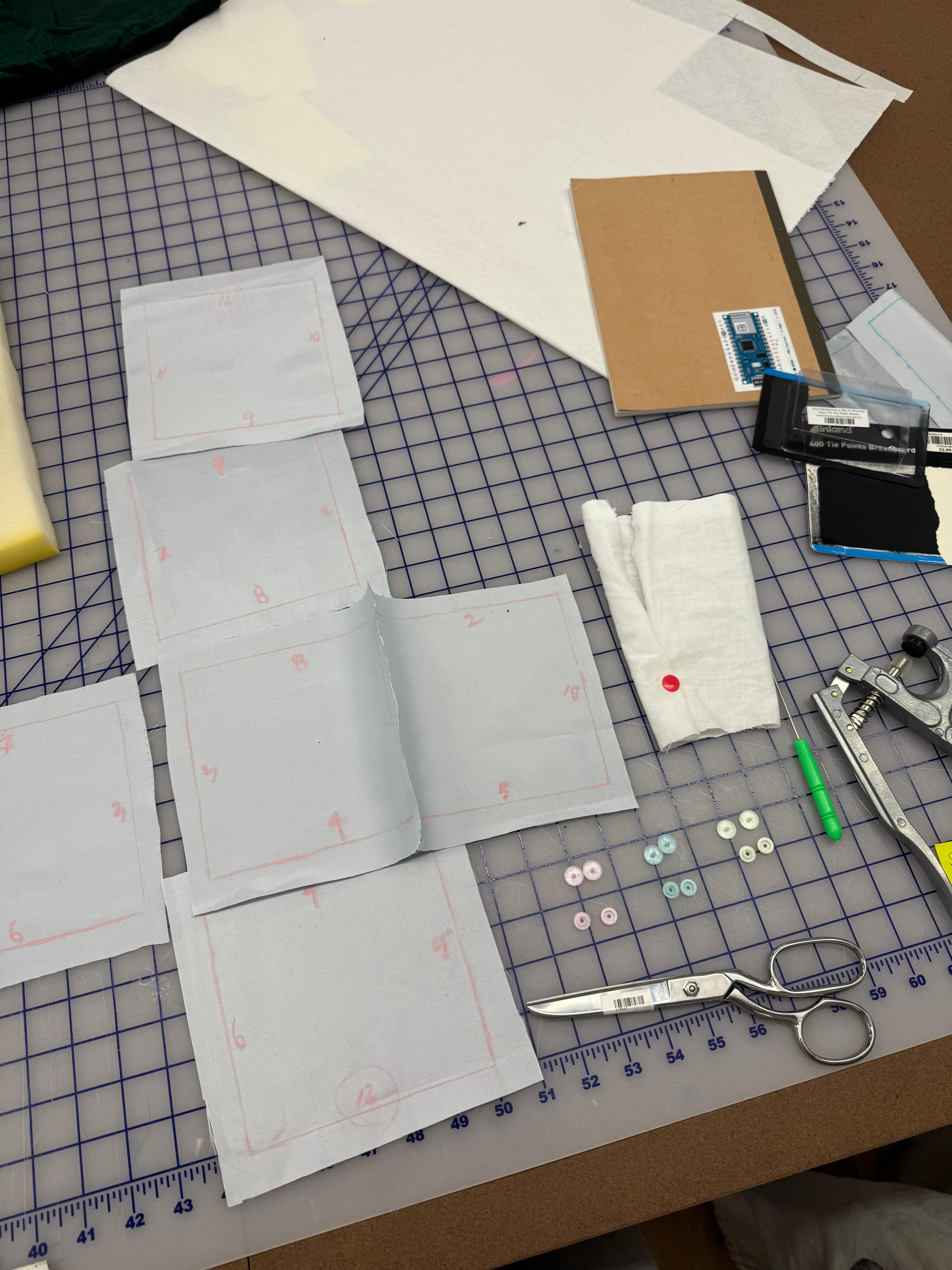
on Tuesday (10/21/2025) I have Office hour with Sao to make a plushie like dice because making the dice plushie like would be the easiest way to figure out the fabrication part at the moment and also it is safter to throw around.
10/21 I went to Micro Center to get the components. (but the soundboard that I got doesn’t seem like it has a direct output pin for the speakers like the one I borrowed from the shop,,, or maybe I’m wrong,, hopefully I’m wrong.. I would have to ask the shop staff to take a look at it ,, )

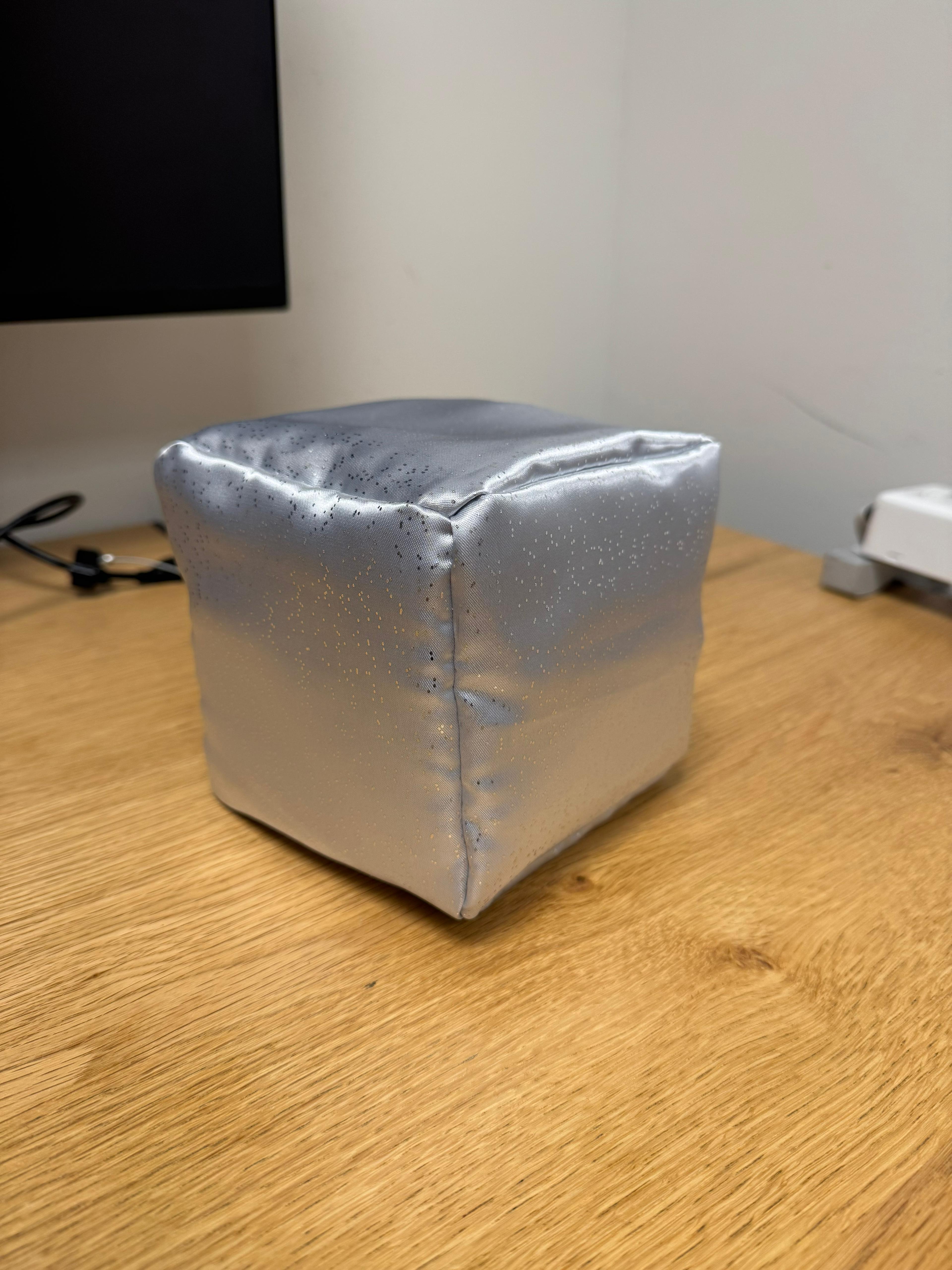
From the office hour with Sao, the resident, I learned how to use the sewing machine, and was able to make a cube out of fabric.
Some reflections from Tom’s note from today’s class:
1) How can I guide people to actually throw the dice?
→ Plan for a system where pressing a button triggers a sound prompt that tells users to share their worries and then roll the dice.
→ Ideally, enable wireless Bluetooth connection between the Arduino and the computer.
→ Instead of using a soundboard, it would be best if the dice’s result sound could also be played through the computer via Bluetooth. (Taking Yushin’s advice that it won’t be stable to put all the mechanics together in a box. It’s best to separate it by using bluetooth connection.)
2) Think about the circumstances where the user throws the die again even before it plays the sound.
1) Guide the users to wait until they hear the answer before proceeding to next action.
2) Update the code so that it will quickly adjust it's behavior by stopping the current output process and detect the new outcome.
→ Justin, the resident, says that Arduino can only act one state at a time,,,
10/22/2025
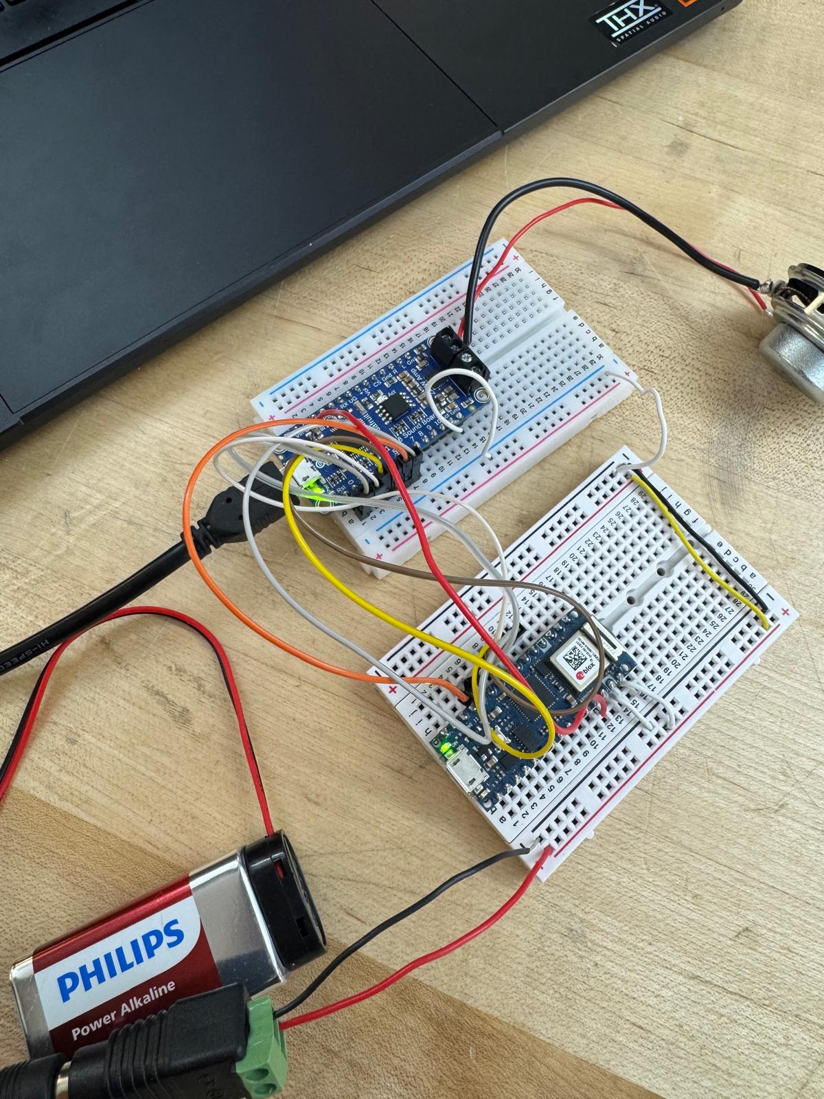
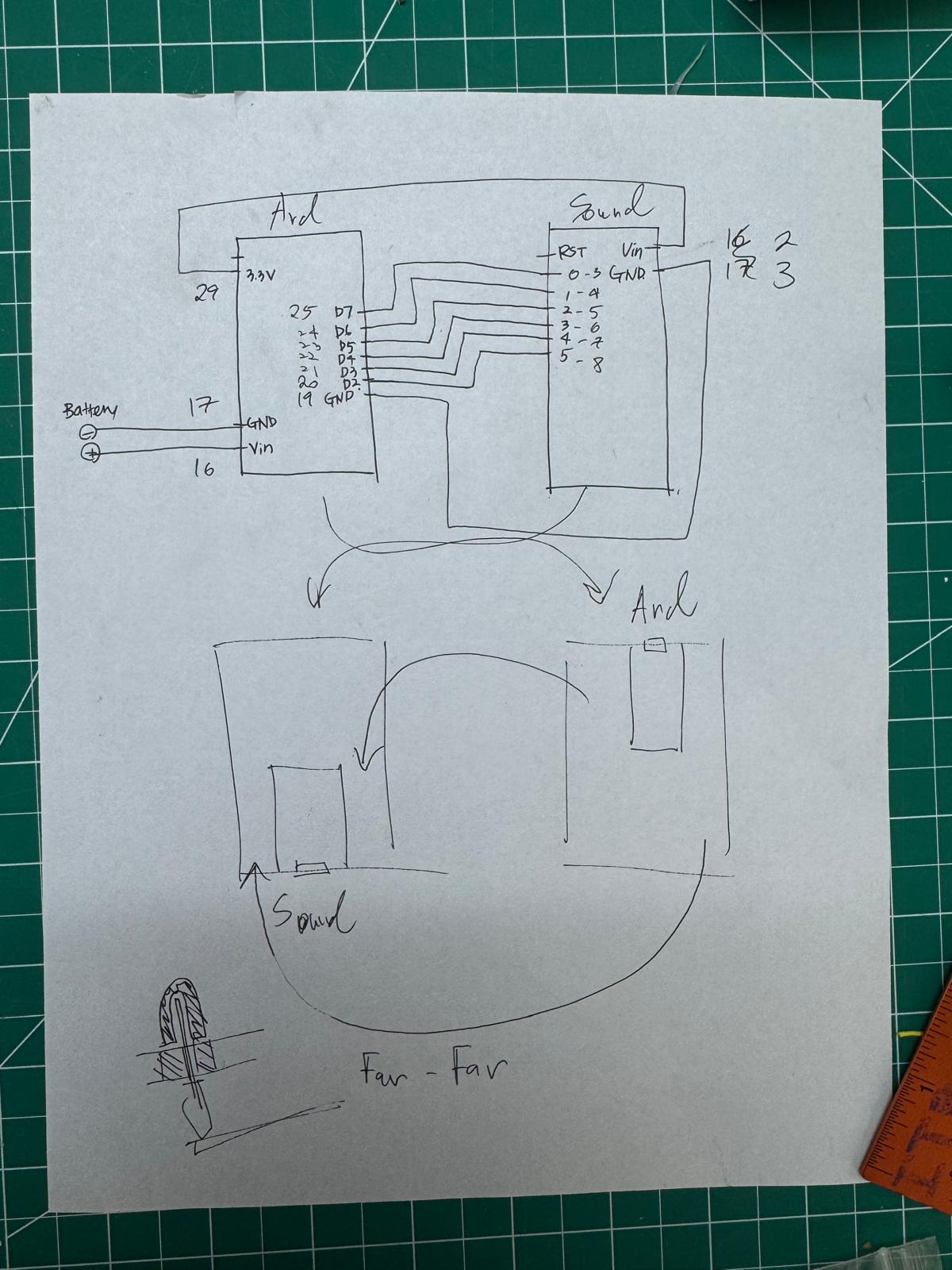
- I figured out the circuit of using two small breadboards with the help of Cody(shot staff). Reading the documents from Adafruit, I realized that the soundboard ideal voltage intake is 3-5.5V. So it’s not the best to connect 9V directly to sound board which I was previously doing.
- But now I have a circuit where I connect the 9V battery to my Arduino and connecting 3.3V output pin to soundboard Vin pin so that soundboard only receives 3.3V.
- Also in order to make those two breadboard work together Cody told me they should share the same ground so I connected each grounds together.
And I drew a circuit.
With the help of Aram, I was able to transfer all the components to the solderable breadboard. I spent most of my day struggling to solder these tinytiny holes,,,, it was hard,, I have metal allergies so I’m feeling terrible…all of my holes on my face are burning (eyeholes and nostrils haha).
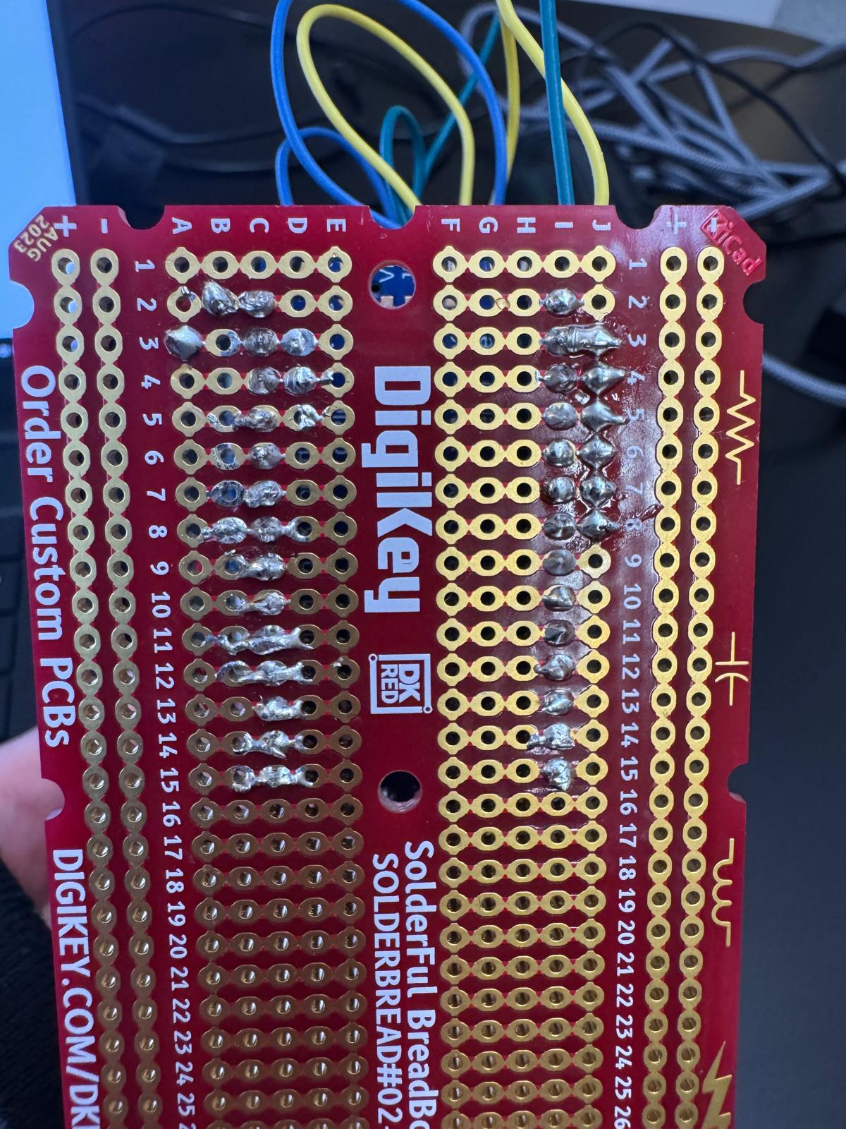
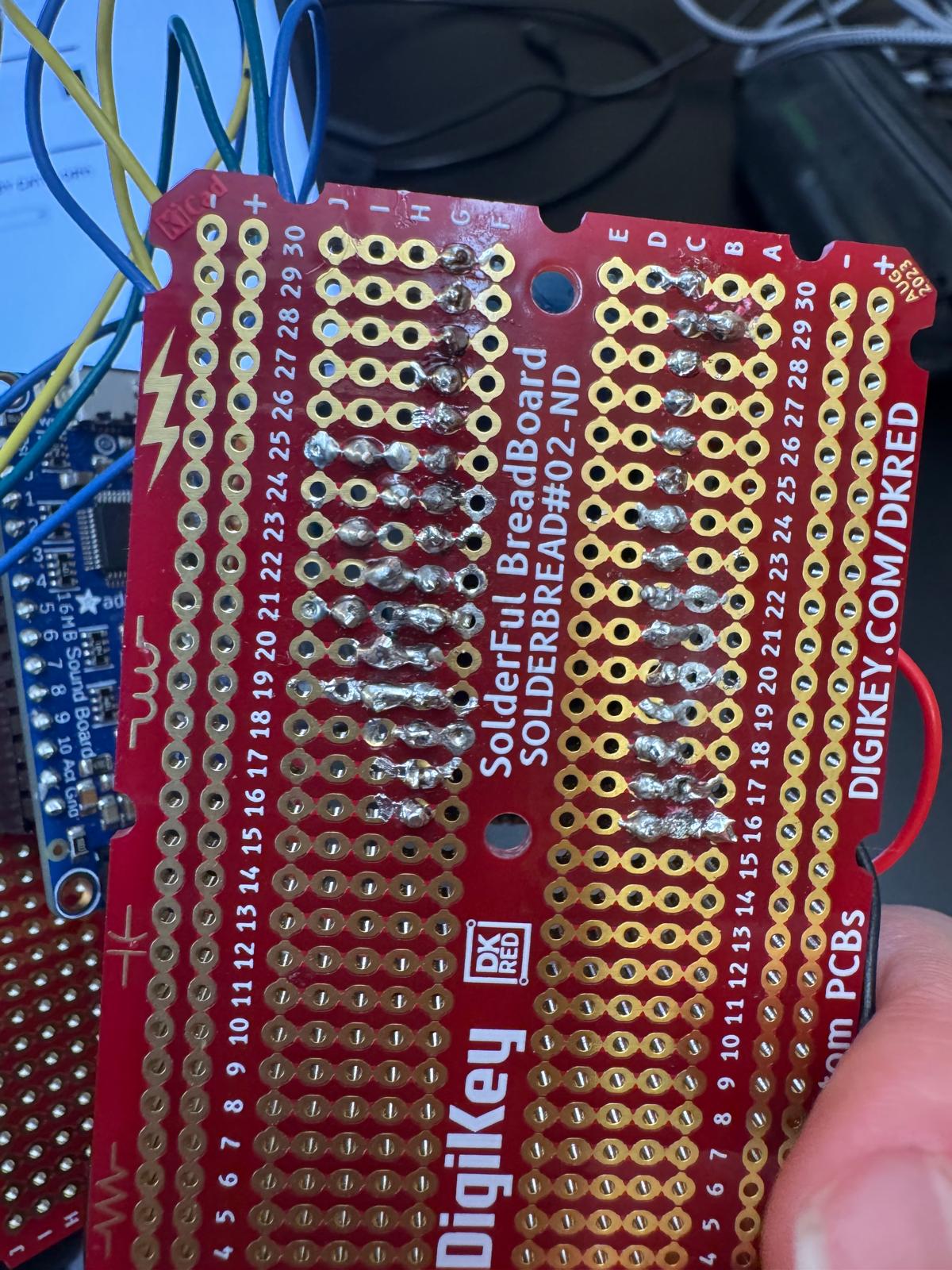 It’s not the best looking solder but it does the job. so I’m satisfied.
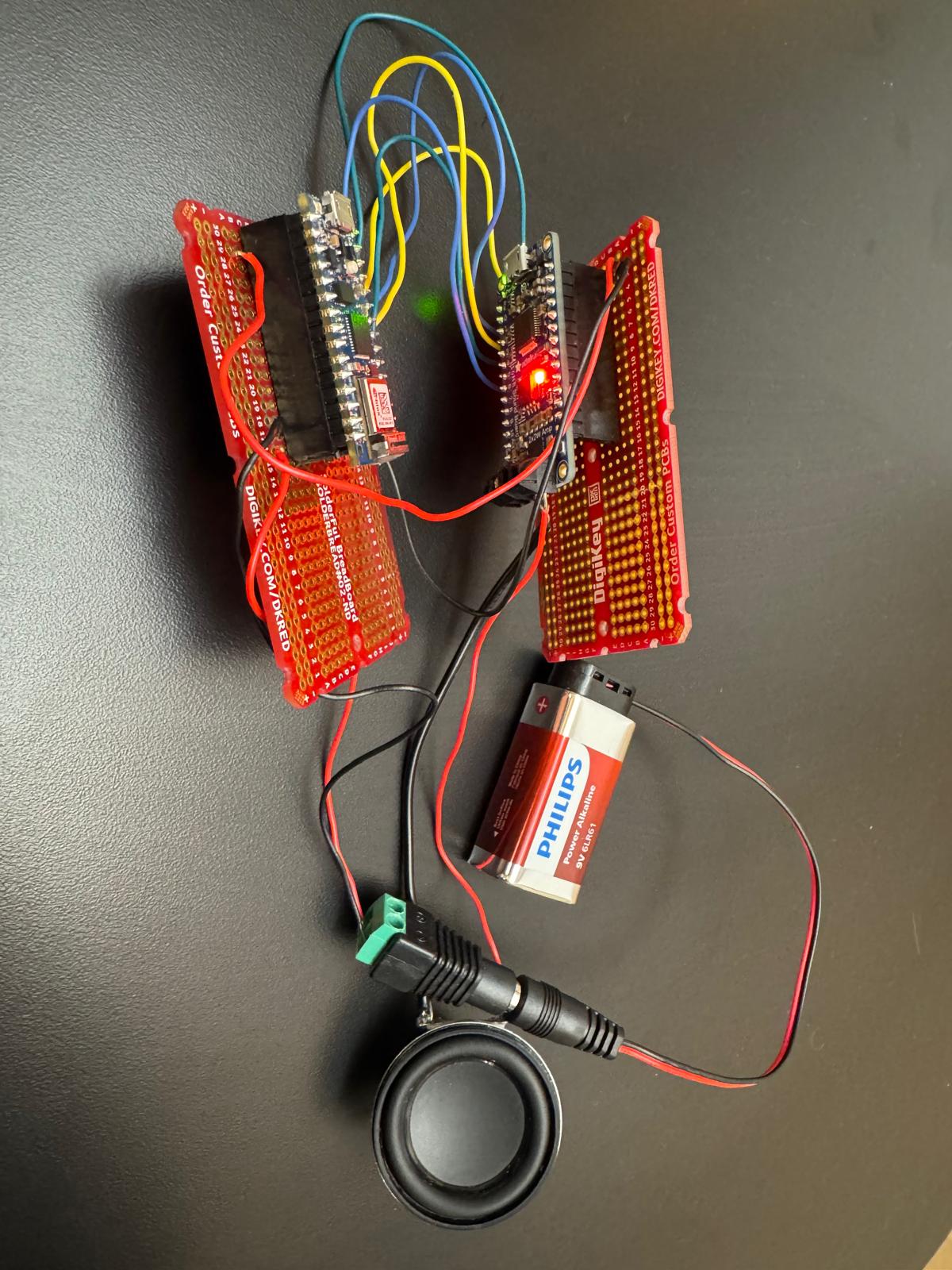 Yay it works!
I booked an office hour with Justin to ask about the Bluetooth connection since i thought it would be better to have the sound coming from the laptop because it would be loud and clear and also easy to guide the users to tell what exactly they should expect to interact with y die. (I want to have a switch that triggers a sound prompt that tells the users to ask question and through the die.)
Justin thought that it would be much easier process to adjust some code to make the volume up by changing the soundboard to Serial mode. so I tried connecting UG and GND pin in soundboard and also connected Arduino TX pin to Soundboard RX pin to change the soundboard to Serial Mode. BUT then the soundboard didn’t play the sound at all. Justin’s guess is that since we changed it to Serial mode it’s no longer reading on/off communication anymore. we tried to write a code that makes sense to serial mode to read but we couldn’t figure out. so I ended up cutting the wires that was connecting UG and GND in soundboard so that we can go back to the original mode. So that was a whole process so we didn’t get to work on connecting Bluetooth today. I have office hour tomorrow with Jeffery and will be asking about Bluetooth connection. and Try to figure out the switch to sound interaction.
Sound board Documentation.: https://learn.adafruit.com/adafruit-audio-fx-sound-board/overview
10/23 Thursday
- Plan: Work on fabrication:
Buy a cardboard box to contain the internal mechanics.use standoffs to firmly stick the breadboard to the box. (does shop have standoffs?)Fill the die inside with cotton and sponge to keep it firm- Test if face detection still works when the dice is thrown. (use the existing shop’s soundboard) https://www.michaels.com/product/mini-kraft-gift-box-by-celebrate-it-10406367
- 2:40 – 3:00pm Jeff F's Office Hours
- connect vol+ pin to switch to ground and test if triggering the vol+ up will make the sound bigger
- if this works, add some code in the setup to trigger volume up when running the code every single time.
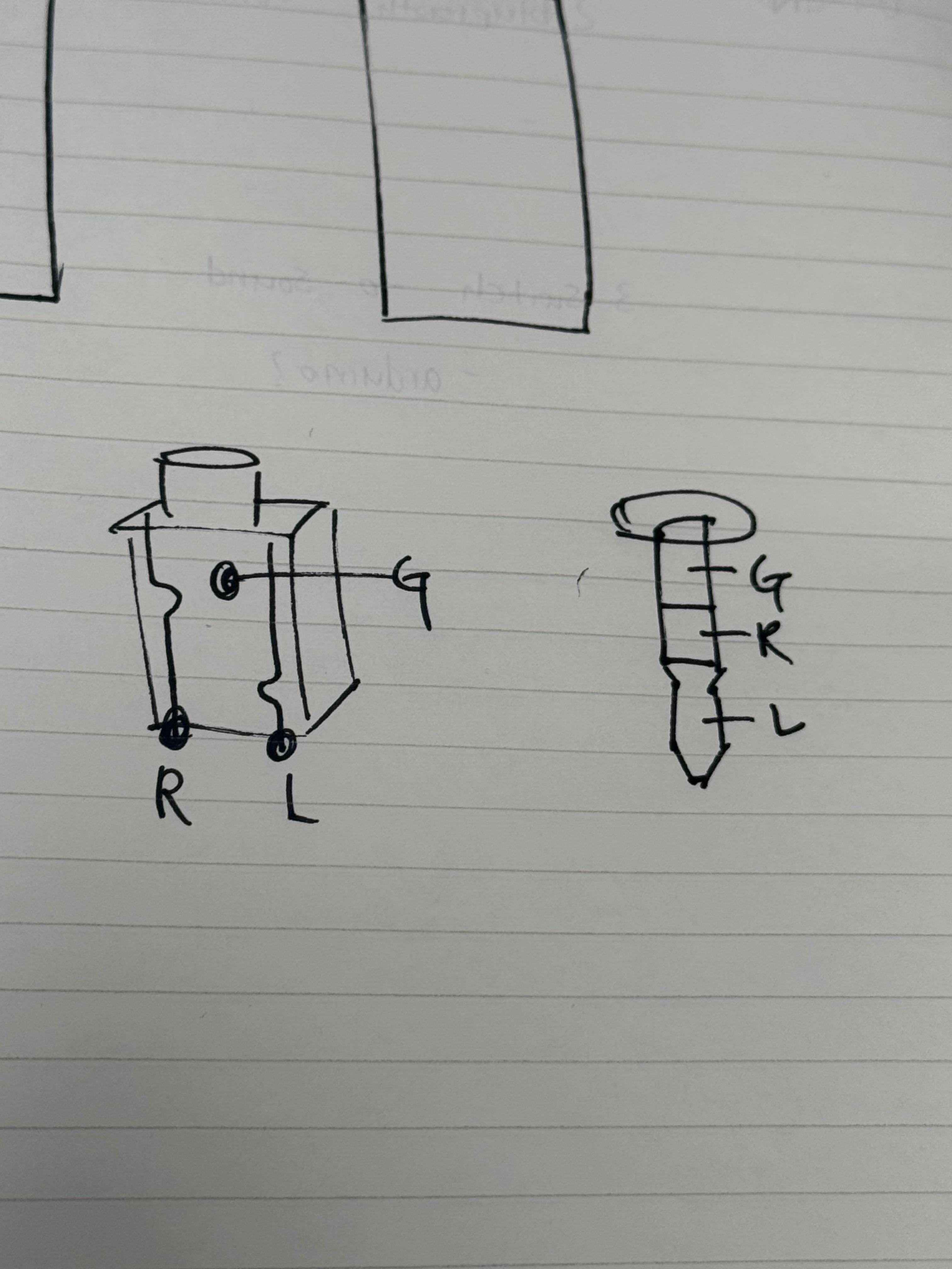
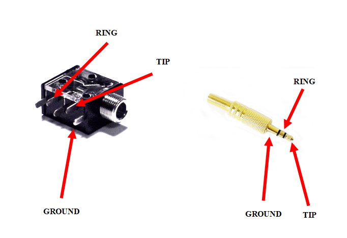
- if this doesn’t work, get a line in/ aux in speaker with headphone jack and connect the ground, R, L to the sound board.
- additional note about the sound file : if I were to record the sound, make sure that the wav file is normalized and has volume compression.
- make a shell that covers the back of the speaker. it will help the sound bigger. Add one more speaker.
- more notes: if I were to use Bluetooth LE to connect my arduino to play sound on my laptop, I would have to know how to use other softwares like p5js or touchdesigner to recieve data from arduino through bluetooth to trigger and play sound. I feel like this is too advanced for me at this point so I will stick to using soundboard for this project. Maybe that could be my Final project.
Question that I didn’t get to ask. during the office hour.
- switch to sound output flow 만들기
- User Guide instruction prompt. sound file.
- I want to make another trigger to play the instruction sound.
i’ll probably have a screen with the text prompt for now. maybe I can make the screen/prompt interact later for my final project.
After the talk with Jeff, I tried option 1.and 2., but it didn’t work. I’m assuming wiring soundboard vol+ pin to arduino digital pin caused the same issue with what I tried last night trying to make the sound board Serial mode which caused it to not receive on/off data from arduino.
So my only option left was to get a speaker that has headphone jack and connect it to the soundboard. Michael Culleton(2nd year) told me I could check out JBL speaker and grab a headphone jack female adapter connecter from the shop yellow bin. So I grabbed all the components and wired up the female adapter and soldered the wires to soundboard(ground, L and R).
Now I have a big enough volume for the sound! YAY!
I carved some sponges and put everything inside! (my circuit with two breadboards, a battery and a speaker). Videos below are Jaye and William doing user testing. William needs more time and patients to become famous.